background image

Hot pixel correction

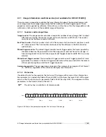
Every pixel that exceeds a certain threshold in the black reference image is marked as a hot
pixel. If the hot pixel correction is switched on, the camera replaces the value of a hot pixel by
an average of its neighbour pixels (see Fig. 4.39).

h o t  

p i x e l

p

n

p

n - 1

p

n + 1

p

n  

=

p

n - 1

+   p

n + 1  

2

Figure 4.39: Hot pixel interpolation

4.6.3

Gain Correction

The gain correction is based on a grey reference image, which is taken at uniform illumination
to give an image with a mid grey level.

Gain correction is not a trivial feature. The quality of the grey reference image
is crucial for proper gain correction.

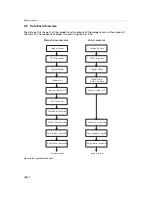
Gain correction algorithm

After configuring the camera with a black and grey reference image, the camera is ready to
apply the gain correction:

1.

Determine the average value of the grey reference image.

2.

Subtract the offset correction matrix from the grey reference image.

3.

Divide the average value by the offset corrected grey reference image.

4.

Pixels that have a grey level higher than a certain threshold are marked as hot pixels.

5.

Store the result in the camera as the gain correction matrix.

6.

During image acquisition, multiply the gain correction matrix from the offset-corrected
acquired image and interpolate the hot pixels (see Section 4.6.2).

Gain correction is not a trivial feature. The quality of the grey reference image
is crucial for proper gain correction.

4.6 Image Correction

73

Summary of Contents for DR1-D1312(IE)-G2

Page 1: ...User Manual MV1 D1312 IE G2 DR1 D1312 IE G2 Gigabit Ethernet Series CMOS Area Scan Camera MAN049 05 2014 V1 4...

Page 2: ......

Page 3: ...responsibility is assumed by Photonfocus AG for its use Photonfocus AG reserves the right to make changes to this information without notice Reproduction of this manual in whole or in part by any mean...

Page 4: ...2...

Page 5: ...RGB Bayer Pattern Filter colour models only 32 4 Functionality 33 4 1 Image Acquisition 33 4 1 1 Readout Modes 33 4 1 2 Readout Timing 35 4 1 3 Exposure Control 38 4 1 4 Maximum Frame Rate 38 4 2 Pix...

Page 6: ...Value 87 4 11 2 Status Line 87 4 12 Test Images 89 4 12 1 Ramp 89 4 12 2 LFSR 89 4 12 3 Troubleshooting using the LFSR 89 4 13 Double Rate DR1 D1312 IE only 92 5 Hardware Interface 95 5 1 GigE Connect...

Page 7: ...Introduction 114 6 10 2 PLC Settings for ISO_IN0 to PLC_Q4 Camera Trigger 116 6 11 Miscellaneous Properties 116 6 11 1 DeviceTemperature 116 6 11 2 PixelFormat 116 6 11 3 Colour Fine Gain Colour camer...

Page 8: ...CONTENTS 6...

Page 9: ...egree of quality 1 2 Contact Photonfocus AG Bahnhofplatz 10 CH 8853 Lachen SZ Switzerland Sales Phone 41 55 451 07 45 Email sales photonfocus com Support Phone 41 55 451 01 37 Email support photonfocu...

Page 10: ...ving been obtained from Photonfocus AG Photonfocus can not be held responsible for any technical or typographical er rors 1 5 Legend In this documentation the reader s attention is drawn to the follow...

Page 11: ...es In this guide the Intel PRO 1000 GT desktop adapter is used The descriptions in the following chapters assume that such a network interface card NIC is installed The latest drivers for this NIC mus...

Page 12: ...w e r S u p p l y a n d I O C o n n e c t o r S t a t u s L E D E t h e r n e t J a c k R J 4 5 Figure 2 1 Rear view of a Photonfocus GigE camera with power supply and I O connector Ethernet jack RJ4...

Page 13: ...e computer before proceeding 4 After the computer has been restarted open the eBUS Driver Installation tool Start All Programs eBUS SDK Tools Driver Installation Tool see Fig 2 2 If there is more than...

Page 14: ...2 How to get started GigE G2 Figure 2 3 PFInstaller components choice 12...

Page 15: ...ttings are described in the tool chapter 1 Open the Network Connections window Control Panel Network and Internet Connections Network Connections right click on the name of the network adapter where t...

Page 16: ...ress automatically For this quick start guide it is recommended to configure the network adapter to obtain an IP address automatically To do this select Internet Protocol TCP IP see Fig 2 4 click the...

Page 17: ...ck on the Advanced tab and click on Jumbo Frames in the Settings list see Fig 2 6 The highest number gives the best performance Some tools however don t support the value 16128 For this guide it is re...

Page 18: ...ows Firewall is used then it can be switched off like this Open the Windows Firewall configuration Start Control Panel Network and Internet Connections Windows Firewall and click on the Advanced tab U...

Page 19: ...rk adapter where the Photonfocus camera is connected and select Properties from the drop down menu that appears A Properties window will open Check the eBUS Universal Pro Driver see Fig 2 8 for maxima...

Page 20: ...o acquire images from the camera and how to modify camera settings 1 Open the PF_GEVPlayer software Start All Programs Photonfocus GigE_Tools PF_GEVPlayer which is a GUI to set camera parameters and t...

Page 21: ...amera is not listed then select the box Show unreachable GigE Vision Devices Figure 2 10 GEV Device Selection Procedure displaying the selected camera 3 Select camera model to configure and click on S...

Page 22: ...the configuration process and connect the camera to PF_GEVPlayer Figure 2 13 PF_GEVPlayer is readily configured 6 The camera is now connected to the PF_GEVPlayer Click on the Play button to grab imag...

Page 23: ...ight is green when an image is being acquired and it is red when serial communication is active 8 Camera parameters can be modified by clicking on GEV Device control see Fig 2 15 The visibility option...

Page 24: ...2 How to get started GigE G2 9 To modify the exposure time scroll down to the AcquisitionControl control category bold title and modify the value of the ExposureTime property 22...

Page 25: ...ns Global shutter Image resolution of up to 12 bit On camera shading correction 3x3 Convolver for image pre processing included on camera monochrome models only Up to 512 regions of interest MROI 2 lo...

Page 26: ...first release had the postfix GB and is not recom mended for new designs The main advantages of the G2 release compared with the GB release are the smaller size better I O capabilities and the suppor...

Page 27: ...Offset and Gain 3x3 Convolver included on camera monochrome models only High blooming resistance isolated trigger input and isolated strobe output 2 look up tables 12 to 8 bit on user defined image r...

Page 28: ...tral range MV1 D1312IE and DR1 D1312IE 320 nm 1000 nm see Fig 3 5 Spectral range MV1 D1312C 390 to 670 nm to 10 of peak responsivity see Fig 3 4 Responsivity MV1 D1312 and DR1 D1312 295 x103 DN J m2 6...

Page 29: ...t 6 Pixel clock frequency 50 MHz 50 MHz Pixel clock cycle 20 ns 20 ns Read out mode sequential or simultaneous Table 3 4 Model specific parameters Footnotes 5 Maximum frame rate full resolution 8 bit...

Page 30: ...12 IE C 100 and DR1 D1312 IE 200 cameras Fig 3 4 shows the quantum efficiency and the responsivity of the monochrome A1312 CMOS sensor displayed as a function of wavelength For more information on pho...

Page 31: ...be used to realize applications in the 900 to 1064 nm region 0 10 20 30 40 50 60 300 400 500 600 700 800 900 1000 1100 Wavelength nm Quantum Efficiency 0 200 400 600 800 1000 1200 Responsivity V J m 2...

Page 32: ...0 0 6 0 0 7 0 0 8 0 0 W a v e l e n g t h n m Q u a n t u m E f f i c i e n c y Q E r e d Q E g r e e n 1 Q E g r e e n 2 Q E b l u e Figure 3 6 Quantum efficiency of the A1312C CMOS image sensor in...

Page 33: ...cut off filter to avoid false colours arising when an infra red component is present in the illumination Fig 3 8 shows the transmssion curve of the cut off filter Figure 3 8 Transmission curve of the...

Page 34: ...umbers in the figure represents pixel position x pixel position y The fix bayer pattern arrangement has to be considered when the ROI configu ration is changed or the MROI feature is used see 4 3 It d...

Page 35: ...time of the current image Readout Mode MV1 D1312 Series Sequential readout available Simultaneous readout available Table 4 1 Readout mode of MV1 D1312 Series camera The following figure illustrates t...

Page 36: ...as possible Free running mode in the sequential readout mode Exposure time of the next image can only start if the readout time of the current image is finished e x p o s u r e r e a d o u t e x p o...

Page 37: ...mera is in free running mode and delivers images without any external control signals The sensor is operated in sequential readout mode which means that the sensor is read out after the exposure time...

Page 38: ...a u s e L i n e p a u s e F i r s t L i n e L a s t L i n e E x p o s u r e T i m e F r a m e T i m e C P R E Figure 4 7 Timing diagram of sequential readout mode mask valid image information The sig...

Page 39: ...e T i m e C P R E Figure 4 8 Timing diagram of simultaneous readout mode readout time exposure time P C L K S H U T T E R F V A L L V A L D V A L D A T A L i n e p a u s e L i n e p a u s e L i n e p...

Page 40: ...lues Example For a 100x100 pixel image there are 100 values transferred within one LVAL active high period or 100 100 values within one FVAL period Line pause Delay before the first line and after eve...

Page 41: ...s involving high intrascene contrast a compression of the upper grey level region can be achieved with the LinLog technology At low intensities each pixel shows a linear response At high intensities t...

Page 42: ...g2 mode a switching between two different logarithmic compressions occurs during the exposure time see Fig 4 13 The exposure starts with strong compression with a high LinLog voltage Value1 At Time1 t...

Page 43: ...vel 8 bit DN V1 15 V1 16 V1 17 V1 18 V1 19 Time1 1000 Time2 1000 Value2 Value1 Figure 4 12 Response curve for different LinLog settings in LinLog1 mode tt V a l u e 1 V a l u e 2 T i m e 1 t e x p 0 V...

Page 44: ...Value1 19 Value2 14 Figure 4 14 Response curve for different LinLog settings in LinLog2 mode 0 20 40 60 80 100 120 140 160 180 200 Typical LinLog2 Response Curve Varying Parameter Time1 Illumination I...

Page 45: ...4 16 Voltage switching in the LinLog3 mode 0 50 100 150 200 250 300 Typical LinLog2 Response Curve Varying Parameter Time2 Illumination Intensity Output grey level 8 bit DN T2 950 T2 960 T2 970 T2 980...

Page 46: ...urations for the region of interest and Table 4 3 presents numerical examples of how the frame rate can be increased by reducing the ROI Both reductions in x and y direction result in a higher frame r...

Page 47: ...amera 2 0 8 P i x e l 2 0 8 P i x e l 2 0 8 P i x e l m o d u l o 3 2 P i x e l 2 0 8 P i x e l m o d u l o 3 2 P i x e l a b Figure 4 19 Possible configuration of the region of interest with MV1 D131...

Page 48: ...1312 x 1082 full resolution 27 fps 54 fps minimum resolution 10224 fps 288 x 1 10672 fps 416 x 1 1280 x 1024 SXGA 29 fps 58 fps 1280 x 768 WXGA 39 fps 78 fps 800 x 600 SVGA 78 fps 157 fps 640 x 480 VG...

Page 49: ...4 x 1 10690 fps not allowed ROI setting 544 x 2 10066 fps 10766 fps 544 x 1082 157 fps 310 fps 1312 x 544 134 fps 266 fps 1312 x 256 282 fps 551 fps 544 x 544 308 fps 600 fps 1024 x 1024 90 fps 181 fp...

Page 50: ...line and w is the width of the region of interest Any ROI settings in x direction exceeding the minimum ROI width must be mod ulo 32 MV1 D1312 IE C 40 MV1 D1312 IE C 80 ROI width w 288 1312 416 1312...

Page 51: ...512 not available not available 416 384 512 448 not available 448 352 512 416 448 not available 480 320 520 384 448 not available 512 288 512 352 448 not available 544 256 512 320 448 384 576 224 512...

Page 52: ...D1312 IE C 40 MV1 D1312 IE C 80 MV1 D1312 IE C 100 1312 x 1082 tro 36 46 ms tro 18 23 ms tro 14 59 ms 1024 x 512 tro 13 57 ms tro 6 78 ms tro 5 43 ms 1024 x 256 tro 6 78 ms tro 3 39 ms tro 2 73 ms Ta...

Page 53: ...s 33 54 fps 37 67 fps Table 4 10 Frame rates of different exposure times sequential readout mode simultaneous readout mode resolution 1312 x 1082 pixel correction on Exposure time DR1 D1312 IE 200 10...

Page 54: ...pping ROIs are allowed See Section 4 3 3 for information on the calculation of the maximum frame rate Fig 4 22 compares ROI and MROI the setups visualized on the image sensor area are displayed in the...

Page 55: ...4 region needs to be readout and a frame rate of 4300 fps can be achieved Without using MROI the resulting frame rate would be 216 fps for a 656x1082 ROI 6 3 6 p i x e l 0 0 x m a x y m a x 2 0 p i x...

Page 56: ...age The rows that will be read out are marked by red lines Row 0 is read out and then every nth row 0 0 1 3 1 1 1 0 8 1 Figure 4 25 Decimation in full image Fig 4 26 shows decimation on a ROI The row...

Page 57: ...eft hand side Figure 4 28 Image example of decimation 3 An example of a high speed measurement of the elongation of an injection needle is given in Fig 4 29 In this application the height information...

Page 58: ...exposure time in external trigger mode can be defined by the setting of the exposure time register camera controlled exposure mode or by the width of the incoming trigger pulse trigger controlled exp...

Page 59: ...input and the strobe output is described in Section 5 5 Settings for Line1 Trigger mode TriggerMode On and TriggerSource Line1 PLC_Q4 Trigger The trigger signal is applied by the Q4 output of the PLC...

Page 60: ...4 Functionality Figure 4 31 Trigger source Figure 4 32 Trigger Inputs Multiple GigE solution 58...

Page 61: ...modes can be used if more than one camera is connected to the same network and need to shoot images simul taneously If all camera are set to Continous mode then all will send the packets at same time...

Page 62: ...ed after n triggers have been accepted SingleFrameRecording Off Camera saves one image on the onboard memory of the IP engine SingleFrameRecording On Camera is ready to accept one trigger according to...

Page 63: ...of the trigger pulse starts the camera states machine which controls the sensor and optional an external strobe output Fig 4 33 shows the detailed timing diagram for the external trigger mode with ca...

Page 64: ...r with Pulsewidth controlled Exposure Time In the external trigger mode with Pulsewidth controlled exposure time the rising edge of the trigger pulse starts the camera states machine which controls th...

Page 65: ...after one single trigger pulse The time between two acquisitions and the number of acquisitions can be configured by a user defined value via the camera software The burst trigger feature works only i...

Page 66: ...r o b e c o n t r o l i n t e r n a l s t r o b e c o n t r o l e x t e r n a l s t r o b e p u l s e o u t p u t t d i s o i n p u t t j i t t e r t t r i g g e r d e l a y t e x p o s u r e t s t r...

Page 67: ...fset non burst mode 400 ns 400 ns ttrigger offset burst mode 500 ns 500 ns texposure 10 s 1 68 s tstrobe delay 0 1 68 s tstrobe offset non burst mode 400 ns 400 ns tstrobe offset burst mode 500 ns 500...

Page 68: ...84 s ttrigger offset non burst mode 200 ns 200 ns ttrigger offset burst mode 250 ns 250 ns texposure 10 s 0 84 s tstrobe delay 600 ns 0 84 s tstrobe offset non burst mode 200 ns 200 ns tstrobe offset...

Page 69: ...fset non burst mode 160 ns 160 ns ttrigger offset burst mode 200 ns 200 ns texposure 10 s 0 67 s tstrobe delay 0 0 67 s tstrobe offset non burst mode 160 ns 160 ns tstrobe offset burst mode 200 ns 200...

Page 70: ...s 0 33 s ttrigger offset non burst mode 80 ns 80 ns ttrigger offset burst mode 100 ns 100 ns texposure 10 s 0 33 s tstrobe delay 0 0 33 s tstrobe offset non burst mode 80 ns 80 ns tstrobe offset burst...

Page 71: ...and the burst configuration The trigger mode must be set to external Trigger TriggerMode On 4 4 8 Strobe Output The strobe output is an isolated output located on the power supply connector that can...

Page 72: ...o s s h a i r s i n s e r t i o n S t a t u s l i n e i n s e r t i o n T e s t i m a g e s i n s e r t i o n A p p l y d a t a r e s o l u t i o n I m a g e o u t p u t M o n o c h r o m e c a m e r...

Page 73: ...mined automatically in the camera Do not set any reference images when gain or LUT is enabled Read the follow ing sections very carefully Correction values of both reference images can be saved into t...

Page 74: ...It may be necessary to adjust the black level offset of the camera In the histogram of the black reference image ideally there are no grey levels at value 0 DN after adjustment of the black level offs...

Page 75: ...ain correction Gain correction algorithm After configuring the camera with a black and grey reference image the camera is ready to apply the gain correction 1 Determine the average value of the grey r...

Page 76: ...cedure to set the grey reference image is described in Section 6 5 The grey reference image must be obtained at uniform illumination Use a high quality light source that delivers uniform illumination...

Page 77: ...c o r r e c t i o n m a t r i x 1 1 2 1 0 9 1 1 2 2 0 9 1 1 1 1 0 8 1 1 0 1 3 0 8 1 0 1 1 2 2 2 g a i n c o r r e c t i o n m a t r i x c o r r e c t e d i m a g e Figure 4 42 Schematic presentation o...

Page 78: ...ffset from the input of the gain block it is possible to avoid the saturation 4 8 Grey Level Transformation LUT Grey level transformation is remapping of the grey level values of an input image to new...

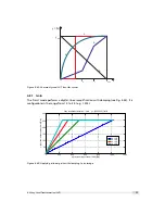
Page 79: ...g see Fig 4 44 It is configurable in the range from 1 0 to 4 0 e g 1 234 0 200 400 600 800 1000 1200 0 50 100 150 200 250 300 Grey level transformation Gain y 255 1023 a x x grey level input value 10...

Page 80: ...onitor screens 0 200 400 600 800 1000 1200 0 50 100 150 200 250 300 Grey level transformation Gamma y 255 1023 x 1 x grey level input value 10 bit DN y grey level output value 8 bit DN 1 0 1 2 1 5 1 8...

Page 81: ...47 Data path through LUT 4 8 4 Region LUT and LUT Enable Two LUTs and a Region LUT feature are available in the MV1 D1312 IE C camera series Both LUTs can be enabled independently see Table 4 18 LUT 0...

Page 82: ...active in region 1 x10 x11 y10 y11 L U T 0 0 0 1 3 1 1 1 0 8 1 L U T 1 x 0 0 x 1 0 x 0 1 x 1 1 y 1 0 y 0 0 y 0 1 y 1 1 Figure 4 48 Overlapping Region LUT example Fig 4 49 shows an example of keyhole...

Page 83: ...of the application of the Region LUT is shown on the right hand side One Region LUT was applied on a small region on the lower part of the image where the brightness has been increased Figure 4 50 Reg...

Page 84: ...ution formula 4 9 2 Settings The following settings for the parameters are available Offset Offset value o see Fig 4 51 Range 4096 4095 Scale Scaling divisor s see Fig 4 51 Range 1 4095 Coefficients C...

Page 85: ...Figure 4 53 3x3 Convolution filter examples 1 Figure 4 54 3x3 Convolution filter examples 1 settings 4 9 Convolver monochrome models only 83...

Page 86: ...4 Functionality A filter called Unsharp Mask is often used to enhance near infrared images Fig 4 55 shows examples with the corresponding settings Figure 4 55 Unsharp Mask Examples 84...

Page 87: ...4095 means white This allows to set any grey level to get the maximum contrast depending on the acquired image The x y position and the grey level can be set via the camera software Figure Fig 4 56 s...

Page 88: ...in both situations The crosshairs however is set differently The crosshairs is not seen in the image on the right because the x and y position is set outside the MROI region 0 0 1 3 1 1 1 0 8 1 x a b...

Page 89: ...all incoming external triggers counter width 8 bit no wrap around Missed burst trigger counter The missed burst trigger counter counts trigger pulses that were ignored by the camera in the burst trig...

Page 90: ...OI Window X Window W 1 40 11 Vertical start position of ROI Window Y In MROI mode this parameter is 0 44 11 Vertical end position of ROI Window Y Window H 1 In MROI mode this parameter is the total he...

Page 91: ...9 Figure 4 59 Ramp test images 8 bit output left 10 bit output middle 12 right 4 12 2 LFSR The LFSR linear feedback shift register test image outputs a constant pattern with a pseudo random grey level...

Page 92: ...ift register test image histogram of the received LFSR test pattern will be flat Fig 4 61 On the other hand a non flat histogram Fig 4 62 indicates problems that may be caused either by the a defectiv...

Page 93: ...d and histogram containing transmission errors In robots applications the stress that is applied to the camera cable is especially high due to the fast movement of the robot arm For such applications...

Page 94: ...uring tasks where sub pixel precision is required Double rate modulation can be turned off for debugging purposes The modulated image is transmitted in mono 8 bit data resolution The modulation is run...

Page 95: ...349 704 365 736 382 768 398 800 415 832 431 864 448 896 464 928 481 960 497 992 514 1024 530 1056 547 1088 563 1120 580 1152 596 1184 613 1216 629 1248 646 1280 662 1312 679 Table 4 21 Width of modul...

Page 96: ...4 Functionality 94...

Page 97: ...n n e c t o r S t a t u s L E D E t h e r n e t J a c k R J 4 5 Figure 5 1 Rear view of the GigE camera 5 2 Power Supply Connector The camera requires a single voltage input see Table 3 5 The camera m...

Page 98: ...changes to an apparently continuous green light with intensity proportional to the ratio of readout time over frame time LED Red Red indicates an active serial communication with the camera Table 5 1...

Page 99: ...a m e r a E l e c t r o n i c I S O L A T O R I S O _ G N D I S O _ P W R 1 2 1 2 p o l H i r o s e C o n n e c t o r 6 8 3 9 7 1 0 1 1 4 5 I O a n d T r i g g e r I n t e r f a c e D C D C D C D C V...

Page 100: ..._INC0 and ISO_INC1 RS 422 inputs have 10 V to 13 V extended common mode range ISO_OUT0 and ISO_OUT1 have different output circuits see also Section 5 5 2 A suitable trigger breakout cable for the Hiro...

Page 101: ...O U T 0 P T C 4 k 7 M a x 3 0 V M a x 0 5 A M a x 0 5 W I S O _ G N D P o w e r M O S F E T I S O _ O U T 1 P T C M a x 3 0 V M a x 0 5 A M a x 0 5 W I s o l a t e d I n t e r f a c e C a m e r a E l...

Page 102: ...n c e d P o w e r F E T 4 7 V 1 0 k I S O _ I N 0 C a m e r a 7 1 2 p o l H i r o s e C o n n e c t o r I S O _ G N D 1 2 Y O U R _ G N D Y O U R _ G N D I n p u t V o l t a g e M a x 3 0 V D C M i n...

Page 103: ...m e r a 3 1 2 p o l H i r o s e C o n n e c t o r I S O _ G N D 1 2 Y O U R _ G N D I S O _ P W R Y O U R _ P W R Y O U R _ G N D C o n t r o l L o g i c Y O U R _ P W R 6 M a x 3 0 V M a x 0 5 A M a...

Page 104: ...connection to ISEO_OUT1 Max imal ratings that must not be exceeded voltage 30 V current 0 5 A power 0 5 W see also Fig 5 9 The type of the Power MOSFET is International Rectifier IRLML0100TRPbF Y O U...

Page 105: ...ISO_INC inputs 5 5 5 Master Slave Camera Connection The trigger input of one Photonfocus G2 camera can easily connected to the strobe output of another Photonfocus G2 camera as shown in Fig 5 11 This...

Page 106: ...3 Power connector PLC ISO_INC1 input signal A4 camera head PLC FVAL Frame Valid signal A5 camera head PLC LVAL Line Valid signal A6 camera head PLC DVAL Data Valid signal A7 camera head PLC Reserved C...

Page 107: ...be installed to use the DR1 HALCON extension package 6 2 PF_GEVPlayer The camera parameters can be configured by a Graphical User Interface GUI tool for Gigabit Ethernet Vision cameras or they can be...

Page 108: ...t properties of the camera head IP properties and properties of the PLC Programmable Logic Controller see also Section 5 6 and document PLC Image stream control Set image stream properties and display...

Page 109: ...control window to apply the property value to the camera A red cross at the upper right corner of the GEV Control Window indicates a parameter error i e a parameter is not correctly set In this case...

Page 110: ...ts all colours equally e g a special grey reference card while clicking on the White Balance button The white balance settings that were made as described in this section are ap plied by the PF_GEVPla...

Page 111: ...vice properties are included in the PFInstaller that can be downloaded from the Photonfocus webpage 6 4 Frequently used properties A property list for every G2 camera is included in the PFInstaller th...

Page 112: ...0 Due to the internal structure of the camera these settings are required for correct calibration 3 Wait until the camera has achieved working temperature 4 Set the property Correction_Mode in categor...

Page 113: ...lues must be stored in flash memory This can be done by clicking on the property Correction_SaveToFlash in category Calibration Wait until the command has been finished i e the property Correction_Bus...

Page 114: ...s described in Section 6 6 2 or Section 6 6 3 For every LUT value the following steps must be done 1 Set LUTIndex in category LUTControl to desired value The LUTIndex corresponds to the grey value of...

Page 115: ...f MROI_Htot This is mandatory as this value is not automatically updated Example pseudo code to set two MROI The resulting total height of the example will be 400 SetFeature MROI_Enable false SetFeatu...

Page 116: ..._Q4 camera trigger is given as an example The resulting configuration is shown in Section 6 10 2 1 Identify the PLC notation of the desired input in Fig 6 4 In our example ISO_IN0 maps to A0 or Line0...

Page 117: ...r i g 3 L o o k u p T a b l e I 1 I 2 I 3 I 4 I 5 I 6 I 7 I 0 E n h a n c e d F u n c t i o n B l o c k Q 0 Q 1 Q 2 Q 3 Q 4 Q 5 Q 6 Q 7 Q 8 Q 9 Q 1 0 Q 1 1 Q 1 5 Q 1 6 Q 1 7 R e m o t e C o n t r o l...

Page 118: ...y IPEngine ProgrammableLogicController 6 11 Miscellaneous Properties 6 11 1 DeviceTemperature The property DeviceTemperature in category DeviceControl shows the value of the temperature sensor that is...

Page 119: ...hannel DigitalBlue Gain applied to the blue channel DigitalGreen2 Gain applied to the green channel on the same row as the red channel To obtain colour gain values using the PF_GEVPlayer follow could...

Page 120: ...unctions for monochrome and for colour DR1 cam eras 6 13 1 Status line in DR1 cameras The newer revisions of the DR1 camera series contain the status line feature see Section 4 11 The status line is s...

Page 121: ...tton Select Output File This is the resulting file after modulation and demodulation of the input image Additionally a difference file can be generated by enabling the corresponding checkbox The value...

Page 122: ...6 Software 120...

Page 123: ...ts the camera adequately from vibration and shock during storage and transport Please either retain this packaging for possible later use or dispose of it according to local regulations 7 1 1 Cameras...

Page 124: ...t to clean the sensor of the most common contaminants Workshop air supply is not appropriate and may cause permanent damage to the sensor 3 If further cleaning is required use a suitable lens wiper or...

Page 125: ...Michael GmbH Germany Methanol Fluid Johnson Matthey GmbH Germany Semiconductor Grade 99 9 min Assay Merck 12 6024 UN1230 slightly flammable and poisonous www alfa chemcat com 2 Propanol Iso Propanol...

Page 126: ...D 0 1 1 6 0 M V 2 D 1 2 8 0 6 4 0 C L 8 S M 2 D 1 0 2 4 8 0 V i s i o n C a m P S D S 1 D 1 0 2 4 4 0 C L D S 1 D 1 0 2 4 4 0 U 2 D S 1 D 1 0 2 4 8 0 C L D S 1 D 1 0 2 4 1 6 0 C L D S 1 D 1 3 1 2 1 6...

Page 127: ...the manufacturer and accompanying said product and the product shall be free from defects in materials and workmanship under normal use The distributor shall not make or pass on to any party any warra...

Page 128: ...8 Warranty 126...

Page 129: ...metry versus Radiometry Photonfocus December 2004 AN026 Application Note LFSR Test Images Photonfocus September 2005 AN030 Application Note LinLog Parameter Optimization Strategies February 2009 GEVQS...

Page 130: ...9 References 128...

Page 131: ...your camera Incorrect voltages will damage or destroy the camera The connection of the input and output signals is described in Section 5 5 A suitable power supply can be ordered from your Photonfocus...

Page 132: ...WR Power supply 5V 24V for output signals Do NOT connect to camera Power 7 I ISO_IN0 IN0 input signal 8 O ISO_OUT1 MISC Q1 output from PLC no Pull up to ISO_PWR can be used as additional output by add...

Page 133: ...n Q0 is not connected to power connector ISO_OUT1 is on Q1 Chapter Software sections DR1_GEVPlayer and Image demodulation added 1 2 April 2012 Chapter How to get started GigE G2 section Hardware Insta...

Reviews: