4 Functionality
:
7
1 0
9
7
9
7
8
7
9
4
3
2
3
4
1
1
9
6
8
4
6
1 0
1
3
4
g r a y r e f e r e n c e
p i c t u r e
a v e r a g e
o f g r a y
r e f e r e n c e
p i c t u r e
)
1
1 . 2
1
0 . 9
1
1 . 2
- 2
0 . 9
1
1
- 1
1
0 . 8
1
1
0
1 . 3
0 . 8
1
0
1
1
- 2
- 2
- 2
=
1
1
1
2
- 1
2
- 2
- 1
0
1
- 1
1
- 1
0
2
0
- 1
0
- 2
0
1
1
- 2
- 2
- 2
-
)
o f f s e t c o r r e c t i o n
m
a t r i x
g a i n c o r r e c t i o n
m
a t r i x
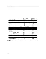
Figure 4.40: Schematic presentation of the gain correction algorithm
Gain correction always needs an offset correction matrix. Thus, the offset correc-
tion always has to be performed before the gain correction.
How to Obtain a Grey Reference Image
In order to improve the image quality, the grey reference image must meet certain demands.
The detailed procedure to set the grey reference image is described in Section
6.5.
•
The grey reference image must be obtained at uniform illumination.
Use a high quality light source that delivers uniform illumination. Standard illu-
mination will not be appropriate.
•
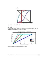
When looking at the histogram of the grey reference image, ideally there are no grey
levels at full scale (4095 DN @ 12 bit). All pixels that are saturated white will not be
properly corrected (see Fig. 4.41).
•
Camera settings may influence the grey level. Therefore, the camera settings of the grey
reference image must be identical with the camera settings of the image to be corrected.
4.6.4
Corrected Image
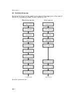
Offset, gain and hot pixel correction can be switched on separately. The following
configurations are possible:
•
No correction
•
Offset correction only
•
Offset and hot pixel correction
•
Hot pixel correction only
•
Offset and gain correction
•
Offset, gain and hot pixel correction
74
Summary of Contents for DR1-D1312(IE)-G2
Page 2: ......
Page 4: ...2...
Page 8: ...CONTENTS 6...
Page 14: ...2 How to get started GigE G2 Figure 2 3 PFInstaller components choice 12...
Page 96: ...4 Functionality 94...
Page 122: ...6 Software 120...
Page 128: ...8 Warranty 126...
Page 130: ...9 References 128...


