7 Hardware Interface
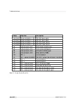
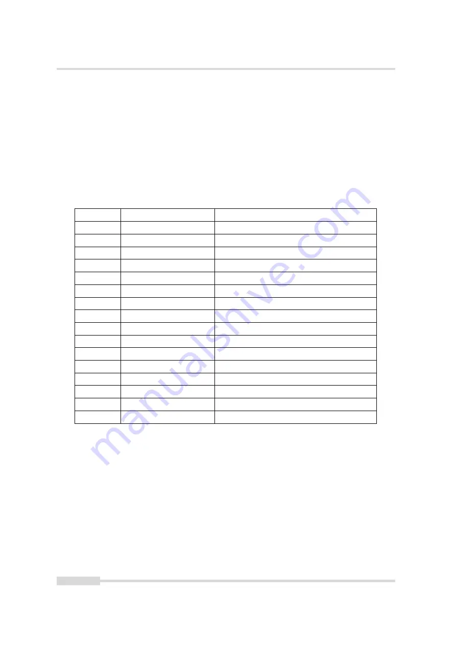
Name
Direction
Description
A0 (Line0)
Power connector -> PLC
ISO_IN0 input signal
A1(Line1)
Power connector -> PLC
ISO_IN1 input signal
A2 (Line2)
Power connector -> PLC
ISO_INC0 input signal
A3 (Line3)
Power connector -> PLC
ISO_INC1 input signal
A4
camera head -> PLC
FVAL (Frame Valid) signal
A5
camera head -> PLC
LVAL (Line Valid) signal
A6
camera head -> PLC
DVAL (Data Valid) signal
A7
camera head -> PLC
Reserved (CL_SPARE)
Q0
PLC ->
not connected
Q1
PLC -> power connector
ISO_OUT1 output signal (signal is inverted)
Q2
PLC ->
not connected
Q3
PLC ->
not connected
Q4
PLC -> camera head
PLC_Q4 camera trigger
Q5
PLC -> camera head
Reserved for future use
Q6
PLC -> camera head
Incremental encoder A signal
Q7
PLC -> camera head
Incremental encoder B signal
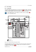
Table 7.2: Connections to/from PLC
98 of 127
MAN075 05/2017 V1.0
Summary of Contents for MV1-D2048-3D06 series
Page 10: ...1 Preface 10 of 127 MAN075 05 2017 V1 0...
Page 12: ...2 Introduction 12 of 127 MAN075 05 2017 V1 0...
Page 26: ...3 How to get started 3D GigE G2 26 of 127 MAN075 05 2017 V1 0...
Page 32: ...4 Product Specification 32 of 127 MAN075 05 2017 V1 0...
Page 66: ...5 Functionality 66 of 127 MAN075 05 2017 V1 0...
Page 82: ...6 Precautions 82 of 127 MAN075 05 2017 V1 0...
Page 120: ...12 Support and Repair 120 of 127 MAN075 05 2017 V1 0...
Page 122: ...13 References 122 of 127 MAN075 05 2017 V1 0...

