5.4 Trigger and Strobe
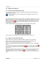
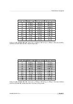
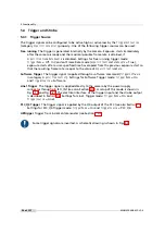
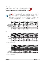
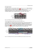
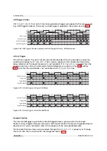
By default the Encoder Position is only generated when
TriggerMode
=
On
and
TriggerSource
=
ABTrigger
. When the property
ABTriggerCountAlways
=True, then the Encoder
Position is generated regardless of the trigger mode.
5.4.10
Counter Reset by an External Signal
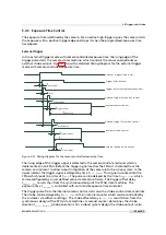
The image counter and the real time counter (timestamp) (see Section 5.10.1) can be reset by
an external signal. Both counters can be embedded into the image by the status line (see
Section 5.10) or their register can be read out. These counters may be used to check that no
images are lost or to ease the synchronisation of multiple cameras.
The external signal to reset the above mentionend counters is selected by the property
Counter_ResetCounterSource
. Available choices are
PLC_Q4
to
PLC_Q7
(see Section 8.11),
Line1
(ISO_IN1) and
ExposureStart
.
ExposureStart
resets the counters at the start of an exposure.
The property
Counter_ResetCounterMode
determines how often the selected source should reset
the counters. The setting
Once
works together with the property
Counter_ResetCounterOnNextTrigger
.
If
Counter_ResetCounterMode
=
Once
, then the counters are reset on the next active edge of the
selected reset source (property
Counter_ResetCounterSource
) after the device is armed with
Counter_ResetCounterOnNextTrigger
=True. The register
Counter_ResetCounterOnNextTrigger
is reset
after the resetting trigger is received.
The setting
Counter_ResetCounterMode
=
Continuous
resets the counters on every occurrence of an
active edge of the reset source without the requirement to arm the device first. This setting is
suited if the reset source signal is different than the camera trigger.
The active edge of the reset input can be set by the property
Counter_ResetCounterSourceInvert
.
If set to
True
, then the rising edge is the active edge, else the falling edge.
Counter reset by an external signal is important if you would like to synchronize
multiple cameras. One signal is applied to all cameras which resets the coun-
ters simultaneously. The timestamps of all cameras are then theoretically syn-
chronous with each other. In practice every camera runs on its own clock source
which has a precision of +/- 30 ppm and therefore the values of the timestamp
(real time counter) of the cameras may diverge with time. If this is an issue, then
the counters could be reset periodically by the external signal.
The counter reset by an external signal feature is not available on all camera
revisions, see Appendix B for a list of available features.
Reset of Individual Counters (ResetCounter_Dual)
If the property ResetCounter_Dual is set to False or if this property is not available, then the
ResetCounter settings apply to the image counter and to the real time counter together.
If ResetCounter_Dual is set to True then CounterReset can be set separately for the image
counter and for the real time counter. In this case the settings without ’RTC’ are applied to the
image counter and the settings with ’RTC’ in its name are applied to the real time counter.
The
ResetCounter_Dual
feature is not be available on all camera revisions, see
Appendix B for a list of available features.
MAN075 05/2017 V1.0
65 of 127
Summary of Contents for MV1-D2048-3D06 series
Page 10: ...1 Preface 10 of 127 MAN075 05 2017 V1 0...
Page 12: ...2 Introduction 12 of 127 MAN075 05 2017 V1 0...
Page 26: ...3 How to get started 3D GigE G2 26 of 127 MAN075 05 2017 V1 0...
Page 32: ...4 Product Specification 32 of 127 MAN075 05 2017 V1 0...
Page 66: ...5 Functionality 66 of 127 MAN075 05 2017 V1 0...
Page 82: ...6 Precautions 82 of 127 MAN075 05 2017 V1 0...
Page 120: ...12 Support and Repair 120 of 127 MAN075 05 2017 V1 0...
Page 122: ...13 References 122 of 127 MAN075 05 2017 V1 0...


