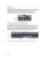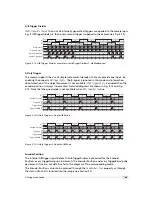
6 Hardware Interface
A suitable power supply can be ordered from your Photonfocus dealership.
For further details including the pinout please refer to Appendix A.
6.3
Status Indicator (GigE cameras)
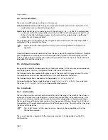
A dual-color LED on the back of the camera gives information about the current status of the
GigE CMOS cameras.
LED Green
It blinks slowly when the camera is not grabbing images.When the camera is
grabbing images the LED blinks at a rate equal to the frame rate. At slow
frame rates, the LED blinks. At high frame rates the LED changes to an
apparently continuous green light, with intensity proportional to the ratio of
readout time over frame time.
LED Red
Red indicates an active serial communication with the camera.
Table 6.1: Meaning of the LED of the GigE CMOS cameras
6.4
Power and Ground Connection for GigE G2 Cameras
The interface electronics is isolated from the camera electronics and the power supply
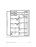
including the line filters and camera case. Fig. 6.2 shows a schematic of the power and ground
connections in the G2 camera models.
.
58
Summary of Contents for MV1-R1280-50-G2 Camera Series
Page 6: ...CONTENTS 6...
Page 10: ...2 Introduction 10...
Page 14: ...3 How to get started GigE G2 Figure 3 3 PFInstaller components choice 14...
Page 30: ...4 Product Specification 30...
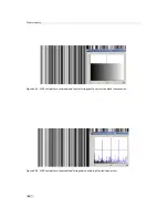
Page 51: ...Figure 5 19 Crosshairs Example with different grey values 5 6 Crosshairs 51...
Page 72: ...6 Hardware Interface 72...
Page 84: ...7 Software 84...
Page 88: ...9 Warranty 88...
Page 90: ...10 References 90...
Page 94: ...B Camera Revisions 94...
Page 95: ...C Document Revision History Revision Date Changes 1 0 April 2015 First version 95...

