4.4.3
Exposure Time Control
Depending on the trigger mode, the exposure time can be determined either by the camera or
by the trigger signal itself:
Camera-controlled Exposure time
In this trigger mode the exposure time is defined by the
camera. For an active high trigger signal, the camera starts the exposure with a positive
trigger edge and stops it when the preprogrammed exposure time has elapsed. The
exposure time is defined by the software.
Trigger-controlled Exposure time
In this trigger mode the exposure time is defined by the
pulse width of the trigger pulse. For an active high trigger signal, the camera starts the
exposure with the positive edge of the trigger signal and stops it with the negative edge.
Trigger-controlled exposure time is not available in simultaneous readout mode.
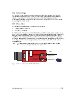
External Trigger with Camera controlled Exposure Time
In the external trigger mode with camera controlled exposure time the rising edge of the
trigger pulse starts the camera states machine, which controls the sensor and optional an
external strobe output. Fig. 4.30 shows the detailed timing diagram for the external trigger
mode with camera controlled exposure time.
e x t e r n a l t r i g g e r p u l s e i n p u t
t r i g g e r a f t e r i s o l a t o r
t r i g g e r p u l s e i n t e r n a l c a m e r a c o n t r o l
d e l a y e d t r i g g e r f o r s h u t t e r c o n t r o l
i n t e r n a l s h u t t e r c o n t r o l
d e l a y e d t r i g g e r f o r s t r o b e c o n t r o l
i n t e r n a l s t r o b e c o n t r o l
e x t e r n a l s t r o b e p u l s e o u t p u t
t
d - i s o - i n p u t
t
j i t t e r
t
t r i g g e r - d e l a y
t
e x p o s u r e
t
s t r o b e - d e l a y
t
d - i s o - o u t p u t
t
s t r o b e - d u r a t i o n
t
t r i g g e r - o f f s e t
t
s t r o b e - o f f s e t
Figure 4.30: Timing diagram for the camera controlled exposure time
The rising edge of the trigger signal is detected in the camera control electronic which is
implemented in an FPGA. Before the trigger signal reaches the FPGA it is isolated from the
4.4 Trigger and Strobe
49
Summary of Contents for SM2-D1312-TI6455
Page 1: ...User Manual SM2 D1312 TI6455 VisionCam PS CMOS DSP Camera MAN060 05 2013 V1 0...
Page 2: ......
Page 4: ...2...
Page 8: ...CONTENTS 6...
Page 48: ...4 Functionality Figure 4 28 Example of decimation 2 on image of injection needle 46...
Page 80: ...4 Functionality 78...
Page 110: ...6 Framework Functionalities 108...
Page 116: ...8 Warranty 114...
Page 118: ...9 References 116...
Page 122: ...A Pinouts 120...
Page 123: ...B Revision History Rev 1 0 May 2013 First version 121...


