background image

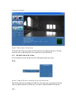
Figure 6.3: Display of temperature in the information area of the web browser

The temperature graph shows the actual temperature of the DSP CPU. The temperature should
not exceed 70° Celsius.

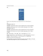
Figure 6.4: Display of the frame rate in the information area of the web browser

Graph of frame rate. The frame rate grabbed by the camera and processed by application is
shown in magenta. It is marked with C. The frame rate displayed over Ethernet is shown in
cyan. It is marked with D.

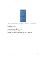
Figure 6.5: Display of Info in the information area of the web browser

Average

The average image value gives the average of an image in 12 bit format (0 .. 4095

DN), regardless of the currently used grey level resolution.

Missed Trigger Counter

The missed trigger counter counts trigger pulses that were ignored by

the camera because they occurred within the exposure or read-out time of an image. In

6.1 Web Server

87

Summary of Contents for SM2-D1312-TI6455

Page 1: ...User Manual SM2 D1312 TI6455 VisionCam PS CMOS DSP Camera MAN060 05 2013 V1 0...

Page 2: ......

Page 3: ...responsibility is assumed by Photonfocus AG for its use Photonfocus AG reserves the right to make changes to this information without notice Reproduction of this manual in whole or in part by any mean...

Page 4: ...2...

Page 5: ...15 2 5 3 Connect camera to JTAG 16 2 5 4 Framework and examples 16 2 5 5 Documentation of the code and libraries 16 2 5 6 microSD card 16 3 Product Specification 17 3 1 Introduction 17 3 2 Hardware Ov...

Page 6: ...y 68 4 9 1 Functionality 68 4 9 2 Settings 68 4 9 3 Examples 68 4 10 Crosshairs monochrome models only 71 4 10 1 Functionality 71 4 11 Image Information and Status Line 73 4 11 1 Counters and Average...

Page 7: ...7 1 Mechanical Interface 109 7 1 1 Cameras with GigE Interface 109 7 2 Optical Interface 110 7 2 1 Cleaning the Sensor 110 7 3 CE compliance 112 8 Warranty 113 8 1 Warranty Terms 113 8 2 Warranty Cla...

Page 8: ...CONTENTS 6...

Page 9: ...egree of quality 1 2 Contact Photonfocus AG Bahnhofplatz 10 CH 8853 Lachen SZ Switzerland Sales Phone 41 55 451 07 45 Email sales photonfocus com Support Phone 41 55 451 01 37 Email support photonfocu...

Page 10: ...ving been obtained from Photonfocus AG Photonfocus can not be held responsible for any technical or typographical er rors 1 5 Legend In this documentation the reader s attention is drawn to the follow...

Page 11: ...ead and IMAGO Technologies vision computer This document is a guideline for programming and understanding the SM2 D1312 IE TI6455 Series VisionCam PS This guide shows you How to get the camera and it...

Page 12: ...y no lense SM2 JTAG connector Figure 2 2 SM2 JTAG adapter and camera 2 2 3 Accessories SM2 JTAG Connector The SM2 JTAG connector is needed to connect the emulator to the DSP of the SM2 camera The JTAG...

Page 13: ...focus Figure 2 4 SM2 power supply SM2 Trigger cables The SM2 trigger cables packages contains two cables 12pol cable for the Hirose power connector 14pol cable for the MDR 14 connector Figure 2 5 SM2...

Page 14: ...able results in transmis sion errors In robots applications the stress that is applied to the GigE cable is especially high due to the fast movement of the robot arm For such applications special drag...

Page 15: ...shown in the camera manual Check the correct supply voltage and polarity Do not exceed the operating voltage range of the camera A suitable power supply can be ordered from your Photonfocus dealershi...

Page 16: ...ou have installed PFInstaller and selected the SM2 package during installation If you don t know the camera IP address use the VIBFinder exe tool you can find it also in the Photonfocus SM2 folder of...

Page 17: ...CS www ti com tool ccstudio The Node Locked Single User N01D cost about 445US There is also a 90day evaluation version CSS FREE avialable The evaluation version has no other limitations More informati...

Page 18: ...aries These documentations are on the microSD card of the SM2 camera 2 5 6 microSD card The microSD card of the SM2 camera contains the following All needed files for CCS development framework source...

Page 19: ...ry high resistance to blooming High dynamic range of up to 120 dB Ideal for high speed applications Global shutter Image resolution of up to 12 bit On camera shading correction 3x3 Convolver for image...

Page 20: ...with all its included features like 1312 x 1082 pixel camera resolution global shutter shading correction and LinLog technology The image processing computer FPGA DSP SDRAM Flash is a module based on...

Page 21: ...tures an internal flash memory of 4 MBytes and a SD Card The internal flash memory is used to store the bootloader some configuration files and the firmware The SD card is used to store image data the...

Page 22: ...st ROI Test pattern LFSR and grey level ramp Shading Correction Offset and Gain 3x3 Convolver included on camera High blooming resistance isolated trigger input and isolated strobe output 2 look up ta...

Page 23: ...79 fA pixel 27 C Full well capacity 90 ke Spectral range SM2 D1312 TI6455 350 nm 980 nm see Fig 3 3 Spectral range SM21 D1312IE TI6455 320 nm 1000 nm see Fig 3 4 Responsivity MV1 D1312 and DR1 D1312 2...

Page 24: ...frame rate full resolution 8 bit SM2 D1312 IE TI6455 80 SM2 D1312 IE TI6455 160 Operating temperature moisture 0 C 50 C 20 80 Storage temperature moisture 25 C 60 C 20 95 Camera power supply 12 V DC...

Page 25: ...onfocus application note AN008 available in the support area of our website www photonfocus com 800 1000 1200 30 40 50 60 V J m m Efficiency QE Responsivity 0 200 400 600 0 10 20 30 200 300 400 500 60...

Page 26: ...e NIR quantum efficiency could be used to realize applications in the 900 to 1064 nm region 0 10 20 30 40 50 60 300 400 500 600 700 800 900 1000 1100 Wavelength nm Quantum Efficiency 0 200 400 600 800...

Page 27: ...t image Readout Mode SM2 D1312 IE TI6455 Series Sequential readout available Simultaneous readout available Table 4 1 Readout mode of SM2 D1312 IE TI6455Series camera The following figure illustrates...

Page 28: ...ing mode in the sequential readout mode Exposure time of the next image can only start if the readout time of the current image is finished e x p o s u r e r e a d o u t e x p o s u r e r e a d o u t...

Page 29: ...out after the exposure time Then the sensor is reset a new exposure starts and the readout of the image information begins again The data is output on the rising edge of the pixel clock The signals F...

Page 30: ...T E R F V A L L V A L D V A L D A T A L i n e p a u s e L i n e p a u s e L i n e p a u s e F i r s t L i n e L a s t L i n e E x p o s u r e T i m e F r a m e T i m e C P R E Figure 4 7 Timing diagra...

Page 31: ...e T i m e C P R E Figure 4 8 Timing diagram of simultaneous readout mode readout time exposure time P C L K S H U T T E R F V A L L V A L D V A L D A T A L i n e p a u s e L i n e p a u s e L i n e p...

Page 32: ...lues Example For a 100x100 pixel image there are 100 values transferred within one LVAL active high period or 100 100 values within one FVAL period Line pause Delay before the first line and after eve...

Page 33: ...intensities inside the pixel In contrast to the classical non integrating logarithmic pixel the LinLog pixel is an integrating pixel with global shutter and the possibility to control the transition b...

Page 34: ...mplest way the pixels are operated with a constant LinLog voltage which defines the knee point of the transition This procedure has the drawback that the linear response curve changes directly to a lo...

Page 35: ...n Fig 4 14 and Fig 4 15 show how the response curve is controlled by the three parameters Value1 Value2 and the LinLog time Time1 Settings in LinLog2 mode enable a fine tuning of the slope in the loga...

Page 36: ...Value2 18 Figure 4 15 Response curve for different LinLog settings in LinLog2 mode LinLog3 To enable more flexibility the LinLog3 mode with 4 parameters was introduced Fig 4 16 shows the timing diagr...

Page 37: ...onse Curve Varying Parameter Time2 Illumination Intensity Output grey level 8 bit DN T2 950 T2 960 T2 970 T2 980 T2 990 Time1 850 Value1 19 Value2 18 Figure 4 17 Response curve for different LinLog se...

Page 38: ...and Table 4 3 present numerical examples of how the frame rate can be increased by reducing the ROI Both reductions in x and y direction result in a higher frame rate The minimum width of the region...

Page 39: ...e configuration of the region of interest with SM2 D1312 IE TI6455 160 CMOS camera Any region of interest may NOT be placed outside of the center of the sensor Examples shown in Fig 4 20 illustrate co...

Page 40: ...80 x 1 10593 fps not allowed ROI setting 544 x 1 10498 fps 11022 fps 544 x 1082 125 fps 249 fps 480 x 1082 141 fps not allowed ROI setting 1312 x 544 107 fps 214 fps 1248 x 544 112 fps 224 fps 1312 x...

Page 41: ...d w is the width of the region of interest Any ROI settings in x direction exceeding the minimum ROI width must be mod ulo 32 SM2 D1312 IE TI6455 80 SM2 D1312 IE TI6455 160 ROI width w 416 1312 544 13...

Page 42: ...800 64 448 128 384 832 32 448 96 384 864 0 448 64 384 896 0 416 32 384 1248 0 64 0 64 1312 0 0 Table 4 5 Some possible ROI X settings SM2 D1312 IE TI6455 series tframe texp tro Typical values of the r...

Page 43: ...joined together and form a single image which is transferred to the frame grabber An individual MROI region is defined by its starting value in y direction and its height The starting value in horizon...

Page 44: ...ity M R O I 0 M R O I 1 M R O I 2 0 0 1 3 1 1 1 0 8 1 0 0 1 3 1 1 1 0 8 1 R O I M R O I 0 M R O I 1 M R O I 2 R O I Figure 4 21 Multiple Regions of Interest Figure 4 22 Multiple Regions of Interest wi...

Page 45: ...1 1 0 8 1 2 0 p i x e l 2 6 p i x e l 2 p i x e l 2 p i x e l 2 p i x e l 1 p i x e l 1 p i x e l C h e m i c a l A g e n t A B C Figure 4 23 Multiple Regions of Interest in hyperspectral imaging 4 3...

Page 46: ...s that will be read out are marked by red lines Row 0 is read out and then every nth row 0 0 1 3 1 1 1 0 8 1 Figure 4 24 Decimation in full image Fig 4 25 shows decimation on a ROI The row specified b...

Page 47: ...eft hand side Figure 4 27 Image example of decimation 3 An example of a high speed measurement of the elongation of an injection needle is given in Fig 4 28 In this application the height information...

Page 48: ...4 Functionality Figure 4 28 Example of decimation 2 on image of injection needle 46...

Page 49: ...the current camera settings then some trigger pulses will be missed A missed trigger counter counts these events This counter can be read out by the user The exposure time in external trigger mode ca...

Page 50: ...applied to the camera by the power supply connector via an optocoupler The input OPTO_IN0 is used RS422 In 0 In the RS422 In 0 trigger mode the trigger signal is applied directly to the camera by the...

Page 51: ...of the trigger pulse starts the camera states machine which controls the sensor and optional an external strobe output Fig 4 30 shows the detailed timing diagram for the external trigger mode with ca...

Page 52: ...rigger with Pulsewidth controlled Exposure Time In the external trigger mode with Pulsewidth controlled exposure time the rising edge of the trigger pulse starts the camera states machine which contro...

Page 53: ...When enabled it starts a predefined number of acquisitions after one single trigger pulse The time between two acquisitions and the number of acquisitions can be configured by a user defined value vi...

Page 54: ...r o b e c o n t r o l i n t e r n a l s t r o b e c o n t r o l e x t e r n a l s t r o b e p u l s e o u t p u t t d i s o i n p u t t j i t t e r t t r i g g e r d e l a y t e x p o s u r e t s t r...

Page 55: ...st mode 200 ns 200 ns ttrigger offset burst mode 250 ns 250 ns texposure 10 s 0 84 s tstrobe delay 600 ns 0 84 s tstrobe offset non burst mode 200 ns 200 ns tstrobe offset burst mode 250 ns 250 ns tst...

Page 56: ...trigger offset non burst mode 100 ns 100 ns ttrigger offset burst mode 125 ns 125 ns texposure 10 s 0 42 s tstrobe delay 0 0 42 s tstrobe offset non burst mode 100 ns 100 ns tstrobe offset burst mode...

Page 57: ...r the slow strobe outputs and are connected with DSP output signals Fig 4 33 shows the different kinds of interfaces in a simplified manner The pinout of the interface connectors are given in Appendix...

Page 58: ...o s s h a i r s i n s e r t i o n S t a t u s l i n e i n s e r t i o n T e s t i m a g e s i n s e r t i o n A p p l y d a t a r e s o l u t i o n I m a g e o u t p u t M o n o c h r o m e c a m e r...

Page 59: ...mined automatically in the camera Do not set any reference images when gain or LUT is enabled Read the follow ing sections very carefully Correction values of both reference images can be saved into t...

Page 60: ...It may be necessary to adjust the black level offset of the camera In the histogram of the black reference image ideally there are no grey levels at value 0 DN after adjustment of the black level off...

Page 61: ...ain correction Gain correction algorithm After configuring the camera with a black and grey reference image the camera is ready to apply the gain correction 1 Determine the average value of the grey r...

Page 62: ...edure to set the grey reference image is described in Section 6 1 5 The grey reference image must be obtained at uniform illumination Use a high quality light source that delivers uniform illumination...

Page 63: ...c o r r e c t i o n m a t r i x 1 1 2 1 0 9 1 1 2 2 0 9 1 1 1 1 0 8 1 1 0 1 3 0 8 1 0 1 1 2 2 2 g a i n c o r r e c t i o n m a t r i x c o r r e c t e d i m a g e Figure 4 40 Schematic presentation o...

Page 64: ...t is possible to avoid the saturation 4 8 Grey Level Transformation LUT Grey level transformation is remapping of the grey level values of an input image to new values The look up table LUT is used to...

Page 65: ...200 400 600 800 1000 1200 0 50 100 150 200 250 300 Grey level transformation Gain y 255 1023 a x x grey level input value 10 bit DN y grey level output value 8 bit DN a 1 0 a 2 0 a 3 0 a 4 0 Figure 4...

Page 66: ...onitor screens 0 200 400 600 800 1000 1200 0 50 100 150 200 250 300 Grey level transformation Gamma y 255 1023 x 1 x grey level input value 10 bit DN y grey level output value 8 bit DN 1 0 1 2 1 5 1 8...

Page 67: ...45 Data path through LUT 4 8 4 Region LUT and LUT Enable Two LUTs and a Region LUT feature are available in the SM2 D1312 IE TI6455 camera series Both LUTs can be enabled independently see 4 11 LUT 0...

Page 68: ...active in region 1 x10 x11 y10 y11 L U T 0 0 0 1 3 1 1 1 0 8 1 L U T 1 x 0 0 x 1 0 x 0 1 x 1 1 y 1 0 y 0 0 y 0 1 y 1 1 Figure 4 46 Overlapping Region LUT example Fig 4 47 shows an example of keyhole...

Page 69: ...of the application of the Region LUT is shown on the right hand side One Region LUT was applied on a small region on the lower part of the image where the brightness has been increased Figure 4 48 Reg...

Page 70: ...ution formula 4 9 2 Settings The following settings for the parameters are available Offset Offset value o see Fig 4 49 Range 4096 4095 Scale Scaling divisor s see Fig 4 49 Range 1 4095 Coefficients C...

Page 71: ...Figure 4 51 3x3 Convolution filter examples 1 Figure 4 52 3x3 Convolution filter examples 1 settings 4 9 Convolver monochrome models only 69...

Page 72: ...4 Functionality A filter called Unsharp Mask is often used to enhance near infrared images Fig 4 53 shows examples with the corresponding settings Figure 4 53 Unsharp Mask Examples 70...

Page 73: ...4095 means white This allows to set any grey level to get the maximum contrast depending on the acquired image The x y position and the grey level can be set via the camera software Figure Fig 4 54 s...

Page 74: ...in both situations The crosshairs however is set differently The crosshairs is not seen in the image on the right because the x and y position is set outside the MROI region 0 0 1 3 1 1 1 0 8 1 x a b...

Page 75: ...nts all incoming external triggers counter width 8 bit no wrap around Missed burst trigger counter The missed burst trigger counter counts trigger pulses that were ignored by the camera in the burst t...

Page 76: ...OI Window X 36 11 Horizontal end position of ROI Window X Window W 1 40 11 Vertical start position of ROI Window Y In MROI mode this parameter is 0 44 11 Vertical end position of ROI Window Y Window H...

Page 77: ...left 10 bit output middle 12 right 4 12 2 LFSR The LFSR linear feedback shift register test image outputs a constant pattern with a pseudo random grey level sequence containing every possible grey le...

Page 78: ...onality Figure 4 58 LFSR linear feedback shift register test image non flat histogram Fig 4 60 indicates problems that may be caused either by the a defective camera or by problems in the grabbing sof...

Page 79: ...d and histogram containing transmission errors In robots applications the stress that is applied to the camera cable is especially high due to the fast movement of the robot arm For such applications...

Page 80: ...4 Functionality 78...

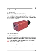
Page 81: ...era operation Figure 5 1 Rear view of the GigE camera 5 2 Power Supply Connector The camera requires a single voltage input see Table 3 4 The camera meets all performance specifications using standard...

Page 82: ...atus LED LED 1 Red Status 1 Indicates status of hardware configuration lights red if the boot process of the camera was successful LED 1 Green Status 2 VIB_SetLED Bit2 value The status can be defined...

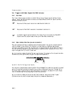
Page 83: ...I S O L A T O R I S O _ G N D I S O _ P W R 1 2 1 2 p o l H i r o s e C o n n e c t o r 6 I O a n d T r i g g e r I n t e r f a c e D C D C D C D C V C C _ 2 V C C _ 1 E S D P r o t e c t i o n E S D...

Page 84: ...g a high efficient input LED coupled with an integrated optical photodiode IC detector The internal shield provides a guaranteed common mode transient immunity of 5 kV s The input is designed for 12 V...

Page 85: ...O P T O _ O U T 0 2 O U T 0 2 O U T _ V C C G N D Figure 5 5 Circuit for the strobe output signals 5 6 Trigger and Strobe Signals for SM2 Cameras 83...

Page 86: ...Additionally to the fail safe feature of the receiver an external fail safe circuitry was implemented for a very robust interface The RS422 outputs are implemented with a MAX3045 which is an ESD prote...

Page 87: ...installed PFInstaller and selected the SM2 package during installation If you don t know the camera IP address use the VIBFinder exe tool you can find it also in the Photonfocus SM2 folder of the PFIn...

Page 88: ...mage and the information part 6 1 2 Information about the Camera In the information area of the web server the following attributes are shown Graph Figure 6 2 Display of CPU load in the information ar...

Page 89: ...y application is shown in magenta It is marked with C The frame rate displayed over Ethernet is shown in cyan It is marked with D Figure 6 5 Display of Info in the information area of the web browser...

Page 90: ...e 6 6 Details of the info button in the web browser The Log viewer shows the last entries of the log Figure 6 7 Display of the histogramer in the web browser in linear mode Figure 6 8 Display of the h...

Page 91: ...dialog window in the web browser 6 1 4 Sensor Figure 6 10 Camera configuration button SENSOR in the web browser This menu is only available for SDK users Please do not use this menu 6 1 5 Camera Figu...

Page 92: ...e number of frames per second can be varied from almost 0 up to the maximum frame rate Thus fewer images can be acquired than would otherwise be possible When Constant Frame Rate is switched off the c...

Page 93: ...e Trigger Pulse Width The exposure time is defined by the pulse width of the trigger signal level controlled exposure This property disables LinLog and simultaneous readout mode Further trigger settin...

Page 94: ...ut set StrobePulseWidth to 0 Strobe Delay ms Delay in milliseconds from the input trigger edge to the rising edge of the strobe output signal Strobe Pulse Width ms The pulse width of the strobe trigge...

Page 95: ...on the grey level resolution Ramp Test image Values of pixel are incremented by 1 starting at each row The pattern depends on the grey level resolution Resolution 8 Bit Grey level resolution of 8 bit...

Page 96: ...T mode to generate the LUT values automatically LUT1 Value With this value the LUT will be calculated depending on the LUT Mode Lut Mode Gain Linear function Y 255 4095 value X Valid range for value 1...

Page 97: ...lues Overlapping is possible LUT0 has higher priority Enable Region LUT Enable the region LUT functionality X X coordinate of region LUT starting from 0 in the upper left corner Y Y coordinate of regi...

Page 98: ...with a ROI or MROI Decimation in y direction transfers every n th row only and directly results in reduced read out time and higher frame rate respectively Decimation Y Decimation value for y directio...

Page 99: ...to 1023 this and all further MROI settings will be ignored H Height of the selected MROI H tot Shows the sum of all MROIs as the total image height After changing a property always press Enter in ord...

Page 100: ...to control the transition between linear and logarithmic mode Section 4 2 2 There are 3 predefined LinLog settings available Alternatively custom settings can be defined in the User defined Mode LinLo...

Page 101: ...ER of the web browser Convolver Enable Enable convolver Presets Select one of the presets or set the coefficients manually Offset Offset value o Range 4096 4095 Scale Scale value s Range 1 4095 Coeffi...

Page 102: ...ge Output the grey reference image that is currently stored in the camera RAM for debugging reasons Calibration Offset FPN Hotpixel Correction The offset correction is based on a black reference image...

Page 103: ...an average between 2200 and 3600 DN Click on the Validation button to check the average If the average is in range the Set Grey Ref button is active Calculate Calculate the correction values into the...

Page 104: ...PRESET of the web browser Load and store settings from the SD card The select box displays the existing settings With the button Apply Pr the selected setting is loaded With the Button Save P the user...

Page 105: ...places the last line of an image with image information please refer the manual for additional information Store as Sensor defaults Store the current configuration in the camera flash memory as the de...

Page 106: ...ve Pic command in the web browser Save button Save the current image to the microSD card Back Step back to previous menu item File type Choose the format of the file to be saved BMP JPG and PNG file f...

Page 107: ...al time clock The clock has a battery Log Show the log of the camera It is also possible to store the log to the microSD card Reboot Reboot the camera DigIO This menu can be used to emulate the trigge...

Page 108: ...server may display a smaller part than the real grabbed image Use the buttons to arrange the displayed image to the desired size You can also click inside the preview window to move the green rectangl...

Page 109: ...functions CDlgApp OnUserIO This function is called from the main task if the App buttons are in front and any of the buttons are clicked CDlgApp OnImage This function is called from the grab task for...

Page 110: ...6 Framework Functionalities 108...

Page 111: ...aging protects the camera adequately from vibration and shock during storage and transport Please either retain this packaging for possible later use or dispose of it according to local regulations 7...

Page 112: ...t to clean the sensor of the most common contaminants Workshop air supply is not appropriate and may cause permanent damage to the sensor 3 If further cleaning is required use a suitable lens wiper or...

Page 113: ...Michael GmbH Germany Methanol Fluid Johnson Matthey GmbH Germany Semiconductor Grade 99 9 min Assay Merck 12 6024 UN1230 slightly flammable and poisonous www alfa chemcat com 2 Propanol Iso Propanol...

Page 114: ...ocus SM2 camera series are in compliance with the below mentioned standards according to the provisions of European Standards Directives EN 61 000 6 3 2001 EN 61 000 6 2 2001 EN 61 000 4 6 1996 EN 61...

Page 115: ...the manufacturer and accompanying said product and the product shall be free from defects in materials and workmanship under normal use The distributor shall not make or pass on to any party any warra...

Page 116: ...8 Warranty 114...

Page 117: ...Photonfocus December 2002 AN007 Application Note Camera Acquisition Modes Photonfocus March 2004 AN008 Application Note Photometry versus Radiometry Photonfocus December 2004 AN026 Application Note L...

Page 118: ...9 References 116...

Page 119: ...your camera Incorrect voltages will damage or destroy the camera The connection of the input and output signals is described in Section 5 6 A suitable power supply can be ordered from your Photonfocus...

Page 120: ...9 I OPTO_IN0 External trigger opto isolated 12 24V DC 10 I OPTO_IN1 External trigger opto isolated 12 24V DC 11 I OPTO_IN2 External trigger opto isolated 12 24V DC 12 PWR IN_GND GND Table A 2 Power su...

Page 121: ...7 O PDIG_OUT2 Differential strobe output RS422 signal 8 PWR VDD 5V 9 I NDIG_IN0 Differential trigger input RS422 signal 10 I NDIG_IN1 Differential trigger input RS422 signal 11 I NDIG_IN2 Differentia...

Page 122: ...A Pinouts 120...

Page 123: ...B Revision History Rev 1 0 May 2013 First version 121...

Reviews: