background image


 OT-7000 RF  

Auto Aligning Straight  

Line Laser System 


User’s Manual 


Summary of Contents for ON-TRAK OT-7000 RF

Page 1: ...OT 7000 RF Auto Aligning Straight Line Laser System User s Manual...

Page 2: ...racy better than 0 001 over distances of 300 feet Using RF spread spectrum communication a closed loop feedback path is established with the reference target to automatically maintain laser alignment...

Page 3: ...th each OT 7000 system Your standard systemconsistsof Alignmentlaser ModelOT 7000LL CentralProcessingUnits ModelOT 7000CPU Transparenttargets ModelOT 7000TTS4 Referencetarget ModelOT 7000TS4 Controlle...

Page 4: ...a notch at the rear of the laser This should be in the up position The rear of the laser is best mounted in a device Model 71 5170 Alignment Telescope Bracket that allows tip tilt movement for the ro...

Page 5: ...product safety eyewear is only required for performing service on the OT 4040 See the service documentation for data on the recommended eye wear Since the OT 4040 does not emit higher than Class 2M le...

Page 6: ...ed It will also flash the serial number of the target that it expects Like the alignment laser the reference target is mounted into a tooling sphere The target center is coincident with the center of...

Page 7: ...eam This is easily accomplished with the OT 7000 system Each target reflects about 4 of the visible beam back towards the laser When the reflected beam is within the 2 5 inch diameter of the laser fac...

Page 8: ...ansparent targets all set up on the factory floor and in the Manual Align mode you can now press Auto align and begin using the system IMPORTANT IF THE BEAM PATH TO THE REFERENCE TARGET IS INTERUPTED...

Page 9: ...parameters that effect the operation of the closed loop process used for auto aligning the laser on the reference target The following text describes some of the user controllable parameters availabl...

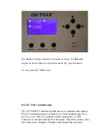
Page 10: ...em Parameters The OT 7000 has an LCD display which allows the user to define the system operation parameters To enter the menu of options press the right arrow key This allows access to the following...

Page 11: ...rease and decrease the value of the selected option Max Dev Is the maximum distance the laser is allowed to travel from center before auto aligning takes place The minimum allowed value is 0 002 The m...

Page 12: ...s is the maximum the laser can travel before it is out of range The minimum value is 0 100 The maximum value is 0 400 To exit press the Menu button Press the Auto Align button to begin using the syste...

Page 13: ...nu key RS 232 USB communication The OT 7000 RF Controller module has two communication options RS 232 communication is facilitated via a 9 pin standard pin 2 to 2 pin 3 to 3 ect RS 232 connector on th...

Page 14: ...Select No 5 Insert the OT 7000 USB Driver CD at the prompt and choose to install from a list or specific location 6 Check the box that says Include this location in search and browse to find the direc...

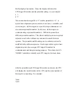
Page 15: ...tems have different preamble numbers This allows multiple systems to operate adjacent to each other without any unwanted crosstalk between systems The preamble and ID settings are in software and can...

Page 16: ...DISCONNECT THE REMOTE SENSOR WHILE THE POWER IS TURNED ON The CPU will display and update the beam position to a resolution of 0 001 If no laser is detected the OT 7000 CPU will return to standby mod...

Page 17: ...ill be relative to the new zero The indicator light above the button will be activated when this feature is in use Display Brightness The OT 7000 CPU has three selectable levels of display brightness...

Page 18: ...tteries When the battery charge state is low the BAT LED will light up The unit should be recharged at this point with the supplied 15V 1 5A wall charger The CPU can continue to operate while it is ch...

Page 19: ...letion power is then shutoff to the laser and controller and the laser is ready for its next use PLEASE DO NOT UNPLUG POWER TO THE CONTROLLER MODULE WHILE THE SYSTEM IS IN THE SHUTDOWN SEQUENCE If pow...

Page 20: ...0LLUltralignlaser Indicatesoff levelconditionsas smallasonearc second Model521SphericalMount Capableofmountingany2 inchdiametercylindricallaserortargetassemblyin themodel560 2Adjustablecupmount Compat...

Page 21: ...mpisdesignedtoholdamodel521sphericalmountina model560 2cupmount Model71 5170AlignmentTelescopeBracket SupportsandprovidesameansforadjustingthepositionoftheOT 7000LLandOT 7000LLUltralignlaser Itcanbeat...

Page 22: ...for non warranty or other work will be supplied if requested before work begins If estimates are not requested repair work will begin as soon as possible Pack the equipment securely in the original ca...

Reviews: