background image

 
EDF ENR PWT 


33,


Rue


Saint


Honoré

 ‐ 

Z.I.


Champfleuri


38300


Bourgoin


Jallieu

 ‐ 

France


Tel


:


33


4


74


93


80


20

 ‐ 

Fax


:


33


4


74


93


80


40


EDF


ENR


PWT


Société


par


actions


simplifiée


à


associé


unique


au


capital


de


37


505


000


 ‐ 


513


281


972


RCS


NANTERRE


Siège


social


:


100


Esplanade


du


Général


de


Gaulle


Cœur


Défense


Tour


B


92932


Paris


La


Défense


cedex

.


D07-P0

6-01

 GB


Ind
ice
 1


   Date 

3

-01-13


User guide for photovoltaic modules 

(UL)


Summary of Contents for PW2350 UL Series

Page 1: ...ax 33 4 74 93 80 40 EDF ENR PWT Soci t par actions simplifi e associ unique au capital de 37 505 000 N 513 281 972 RCS NANTERRE Si ge social 100 Esplanade du G n ral de Gaulle C ur D fense Tour B 9293...

Page 2: ...ling system installation or compliance or non compliance with the instructions set forth in this manual 2 0 SAFETY PRECAUTIONS Warning All instructions should be read and understood before attempting...

Page 3: ...ith an AM1 5 spectrum and cell temperature of 25 C The detailed electrical and mechanical characteristics of EDF ENR PWT crystalline silicon PV modules can be found in table A 2 of this manual see Ann...

Page 4: ...with sharp objects as scratches may directly affect product safety Do not leave a module unsupported or unsecured Do not change the wiring of bypass diodes Keep all electrical contacts clean and dry 5...

Page 5: ...ted together to create a voltage higher than the permitted maximum system voltage even under the worst local temperature conditions Similar electrical performance modules should be connected in the sa...

Page 6: ...op and ensure conductor ampacity complies with local regulations such as NEC 690 8 D Cable protection Secure the cables to the mounting system using UV resistant cable ties Protect exposed cables from...

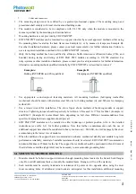
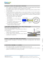
Page 7: ...ed for Photowatt modules as described below For alternative CSA qualified grounding methods please refer to Annex B Method Bolt Nut with teeth Cup washer When diameter of the grounding holes is 5mm CS...

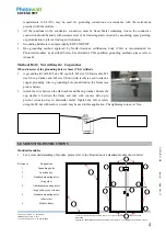
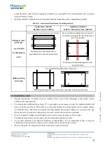
Page 8: ...lified Clamping on INTERTEK qualified Use appropriate corrosion proof fastening materials All mounting hardware bolt spring washer flat washer nut should be made with stainless steel M6 size for bolti...

Page 9: ...below the module Mounting rails should run parallel to the short side frame Bolting on long side frame Use 4 standard mounting holes long side Mounting rails may run perpendicularly or parallel to the...

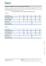
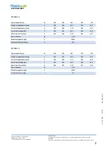
Page 10: ...pecifications are subject to change without notice Table A Specifications for PW series photovoltaic modules under STC PW2350 UL Typical power Pmax W 220 225 230 235 240 Voltage at typical power Vmp V...

Page 11: ...r Vmp V 35 8 35 9 36 0 36 1 36 3 Current at typical power Imp A 7 96 8 08 8 19 8 30 8 41 Open circuit voltage Voc V 44 3 44 4 44 5 44 6 44 8 Short circuit current Isc A 8 53 8 64 8 76 8 87 8 97 Power...

Page 12: ...le Once crimped each terminal should be visually checked according to the following points 1 The insulator jacket is correctly crimped in the first collar 2 The conductor core is correctly crimped in...

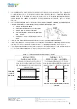
Page 13: ...r cast shadow on the front glass 3 Not to damage the surface of the frame 4 To ensure the clamps overlap the module frame by at least 5 mm 5 To ensure the clamps overlap length is at least 40 mm Clamp...

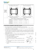
Page 14: ...SYSTEMS The mounting method has been qualified by EDF ENR PWT and certified by CSA Insertion methods will vary and are dependent on the mounting structures Follow mounting guidelines recommended by t...

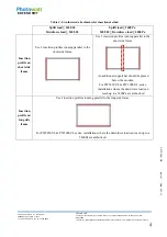
Page 15: ...Pa Downforce load 2400 Pa Uplift load 2400 Pa 2400 Pa Downforce load 4000 Pa Insertion profile on short side frame Use 2 insertion profiles running parallel to the short side frame Use 2 insertion pr...

Reviews: