D84-P06-01 GB R3
21/04/2021
www.photowatt.com
4
each product's datasheet. Main electrical characteristics
under STC are also stated on each module label. Please
refer to the datasheet or the product nameplate for the
maximum system voltage.
Under certain conditions, a module may produce more
current or voltage than its Standard Test Conditions rated
power. As a result, the module short-circuit current under
STC should be multiplied by 1.25, and a correction factor
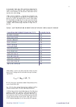
should be applied to the open-circuit voltage (see Table
1 below), when determining component ratings and ca-
pacities.
TABLE 1. LOW TEMPERATURE CORRECTION FACTORS FOR OPEN-CIRCUIT VOLTAGE
Lowest Expected Ambient Temperature (°C/°F)
Correction factor
24 to 20 / 76 to 68
1.02
19 to 15 / 67 to 59
1.04
14 to 10 / 58 to 50
1.06
9 to 5 / 49 to 41
1.08
4 to 0 / 40 to 32
-1 to -5 / 31 to 23
1.10
1.12
-6 to -10 / 22 to 14
1.14
-11 to -15 / 13 to 5
1.16
-16 to -20 / 4 to -4
1.18
-21 to -25 / -5 to -13
1.20
-26 to -30 / -14 to -22
1.21
-31 to -35 / -23 to -31
1.23
-36 to -40 / -32 to -40
1.25
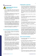
C
voc
= 1-
α
Voc
x (25 - T)
T
(°C) is the lowest expected ambient temperature at the
system installation site
α
Voc
(%/ºC) is the voltage temperature coefficient of the
selected module (refer to corresponding datasheet)
OCPD rating selection should be done per the following
guidance, where the minimum OCPD rating possible is
determined by calculating the expected maximum cir-
cuit current for the PV system, and the maximum OCPD
rating constrained by the IEC 61215: 2016 and UL 1703:
2018 standard requirements for the certified PV modules.
Alternatively, a more accurate correction factor for the
open-circuit voltage can be calculated using the follow-
ing formula:


