FASTCAM-512PCI Hardware Manual
- 14 -
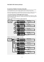
Connection for Multiple Camera Sync Operation
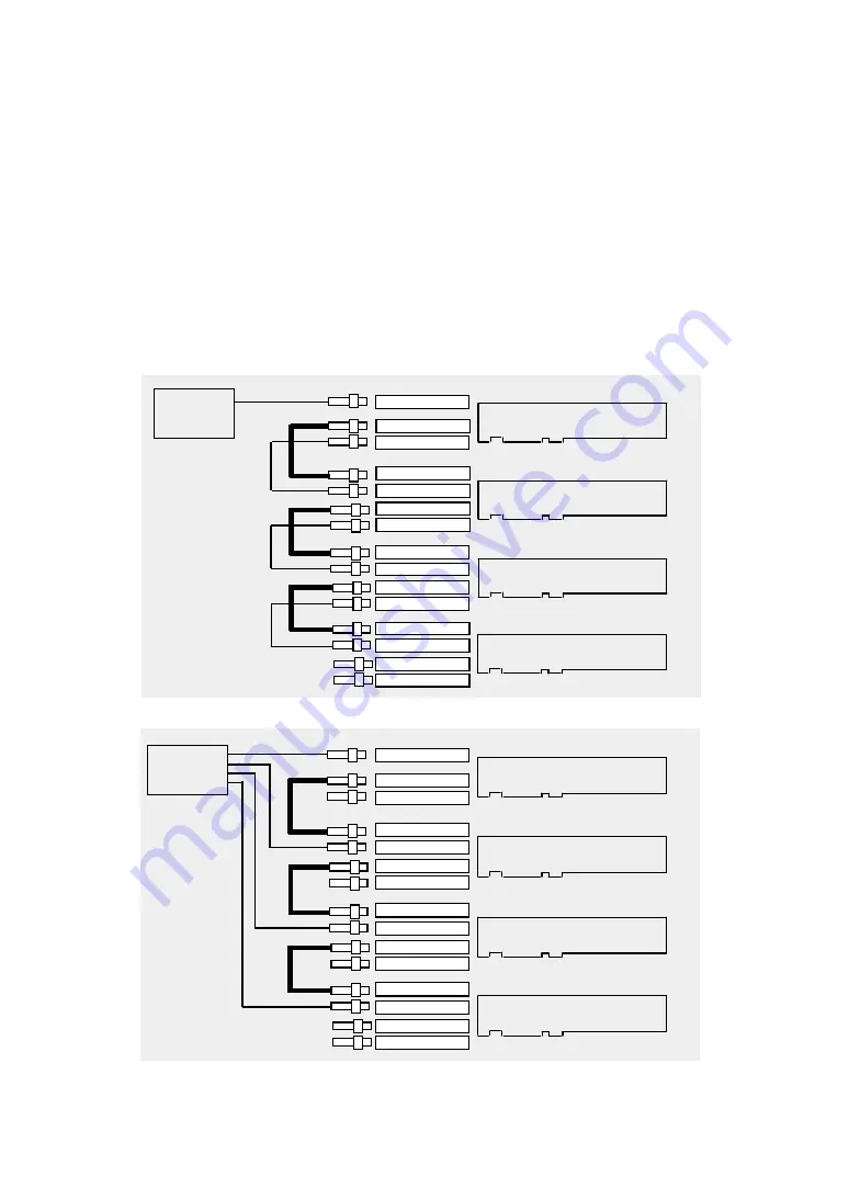
The following figures show how to connect between master and slave boards for sync recording.
Connect cables so that the sync and trigger signals are fed to the input of slave boards.
Note: External signal cables have JJ (male-female conversion) connectors. Remove them before
connecting to respective boards. Retain the removed conversion connectors for future use.
1. Connection between FASTCAM-512PCI Cameras
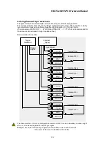
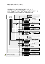
The following two figures show sync cable connection for multiple PCI R2 cameras. Due to delay
of signals between the boards, Example 2 is recommended, except for using software trigger (see
Section 3.3. Timing Charts).
Example 1: Basic Connection (Good for software triggering)
Master Mode
Slave Mode
Slave Mode
Slave Mode
Camera ID: 0
Camera ID: 1
Camera ID: 2
Camera ID: 3
SYNC IN
SYNC OUT
TRIG OUT
T-TTL IN
SYNC OUT
TRIG OUT
SYNC IN
SYNC OUT
TRIG OUT
T-TTL IN
SYNC IN
SYNC OUT
TRIG OUT
T-TTL IN
T-TTL/SW IN
Trigger
Generator
Master Mode
Slave Mode
Slave Mode
Slave Mode
Camera ID: 0
Camera ID: 1
Camera ID: 2
Camera ID: 3
SYNC IN
SYNC OUT
TRIG OUT
T-TTL/SW IN
SYNC OUT
TRIG OUT
SYNC IN
SYNC OUT
TRIG OUT
T-TTL/SW IN
SYNC IN
SYNC OUT
TRIG OUT
T-TTL/SW IN
T-TTL/SW IN
Example 2: Parallel Trigger Input (Recommended)
Trigger
Generator

