background image


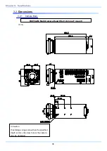
FASTCAM Multi Camera Head HS-01 (G type F mount) with Tripod Adapter 


(mm) 


92.8

6

9

.

9

0.5

1

2

39

3

9

.

3

74.8

59.8

45.8

38.8

4

8

86.8

(0.5)

9.1

6

9

32.8

17.8

2

8

60

3

5

.

5

4

5

35.9

38.8

190.4

150.9

4-M4 DEPTH6

φ

4.5 DEPTH5.5

6-M3 DEPTH4

1/4-20UNC DEPTH6

3/8-16UNC DEPTH6


Caution 

If installing a longer screw than the specified 

depth (in mm), its screw hole or the camera 

may be damaged. 


37 


FASTCAM Multi Camera Head HS-01 

Summary of Contents for HS-01

Page 1: ...F FA AS ST TC CA AM M M Mu ul lt ti i C Ca am me er ra a H He ea ad d H HS S 0 01 1...

Page 2: ...nd to comply with the limits for a Class A digital device pursuant to part 15 of the FCC Rules These limits are designed to provide reasonable protection against harmful interference when the equipmen...

Page 3: ...rd and refer back to it when necessary Manual Notation The following icons and symbols are used in the explanations in this manual Icon Symbol Description This symbol indicates content that should alw...

Page 4: ...the system and the procedure for connecting each component of the system Chapter 2 Function This chapter explains the system s functions Refer to the Photron FASTCAM Viewer User s Manual for additiona...

Page 5: ...pay careful attention to the content of the safety precautions when using the system This symbol indicates actions that carry the risk that a person could receive a serious injury This symbol indicat...

Page 6: ...There are high voltages inside the system that can cause electric shock Do not plug in or unplug the power cord with wet hands Doing so can cause electric shock This chapter lists the contact informa...

Page 7: ...or steam or in a location with a lot of humidity or dust Oil moisture and dust conduct electricity which can cause a fire or electric shock Do not obstruct the air intake and exhaust port when the sy...

Page 8: ...trical and electronic equipment EEE and batteries and accumulators Improper handling of this type of waste could have a possible impact on the environment and human health due to potentially hazardous...

Page 9: ...er technology Please discharge any electrostatic build up in your body by touching a grounded metallic Surface before working near the camera sensor Very gently use only clean and dry air to remove du...

Page 10: ...ch other to avoid dirt and pollution and to keep clean inside The camera cable includes optics fibers If dust or dirt is in inside of a connector it may cause a communication error Keep clean the insi...

Page 11: ......

Page 12: ...4 2 CENTER Mode 14 2 4 3 END Mode 15 2 4 4 MANUAL Mode 15 2 4 5 RANDOM Mode 15 2 4 6 RANDOM RESET Mode 16 2 4 7 RANDOM CENTER Mode 17 2 4 8 RANDOM MANUAL Mode 18 2 5 LOW LIGHT Mode 19 2 6 VARIABLE Set...

Page 13: ...olution 30 3 1 4 Shutter Speed List 33 3 1 5 Recordable Image Count Resolution 34 3 1 6 Recordable Time Resolution 35 3 2 Dimensions 36 3 2 1 Camera Body 36 3 2 2 Clearance for Camera Cable Connection...

Page 14: ......

Page 15: ...Chapter 1 Overview 1 1 Product Overview and Features 1 2 System s Components and Accessories 1 3 Part Names 1 4 Connection 1 FASTCAM Multi Camera Head HS 01...

Page 16: ...control and component technology development science medical and aerospace The Multi camera head HS 01 has adopted a robust design where circuit boards are completely sealed from the outside and a FAN...

Page 17: ...Accessories Options Connect this camera to the FASTCAM Multi Main Unit for operation The following optional items are available to choose from as of March 2015 1 FASTCAM Multi Camera Cable 5m 102481...

Page 18: ...FASTCAM Multi Camera Head HS 01 type 200K M Color FASTCAM Multi Camera Head HS 01 type 200K C Export controlled model type 200K is subject to restriction on the frame rate and shutter speed Subject to...

Page 19: ...cessive force 1 3 1 Camera Head This is a camera head specifically designed to shoot a fast moving object It has imaging function only and the image data is transferred via the camera cable to the mem...

Page 20: ...le Connector Power Connector For LED Light Laser Pointer Switch Front Back FASTCAM Multi Camera Head HS 01 G type F mount LED Light Switch Power Connector for LED Light LED Light Switch and Laser Poin...

Page 21: ...nt by acquiring a Micro Four Thirds Lens Option for FASTCAM Mult How to change the lens mount G type F mount C mount 1 Remove the four M3 Hex Socket Cap screws using the hexagonal wrench 2 Remove the...

Page 22: ...e the cap from the camera cable Connect the caps each other to avoid dirt and pollution and to keep clean inside 3 Connect the camera cable Make sure of the connector on the camera head and Main Unit...

Page 23: ...he processor or the camera head Be sure to verify if the camera cable has been correctly and firmly inserted If the camera cable is disconnected for any reason while the camera is active an error will...

Page 24: ...Chapter 1 Overview 10...

Page 25: ...IGHT Mode 2 6 VARIABLE Setting 2 7 White Balance Adjustment Color Model Only 2 8 Color Enhancement Function Color Model Only 2 9 Look Up Table LUT Operations 2 10 Edge Enhancement Function 2 11 Partit...

Page 26: ...tal resolution is applied Frame Rate cannot be increased This specification is different from other systems Please refer to 3 1 3 Frame Rate and Resolution page 30 for available frame rate Export cont...

Page 27: ...Viewer User s Manual for the details of the setup A minimum exposure time depends on a set up frame rate Export controlled model type 200K is subject to certain restriction on the shutter speed Frame...

Page 28: ...il the memory is full and then recording ends This mode is suitable for taking images of high speed phenomena when what will happen and when it happens is known in advance For example in a situation w...

Page 29: ...ut the proportion of time before and after the trigger can be set as required For example in a situation with a maximum record time of two seconds 0 5 seconds before and 1 5 seconds after the trigger...

Page 30: ...gger is input but the internal record timing signal is independent and it operates regardless of when the trigger is input For this reason there may be situations where the start time of the first fra...

Page 31: ...produced for each cycle or occurrence and you want to check the action before and after the trigger timing The number of frames recorded each time the trigger is input can be set as desired in one fr...

Page 32: ...ct which is an irregular and repeated phenomenon which can have a trigger output produced for each cycle or occurrence and you want to check the action before and after the trigger timing The number o...

Page 33: ...te and resolution can be set to the desired value following the conditions listed below FRAMERATE can be set from 54 frame rates between 50 fps and 750 000 fps The size and horizontal position of the...

Page 34: ...ance These methods are explained in this section 2 7 1 Using Preset White Balance Color Model Only With the system there are two types of white balance presets 5100K 3100K for use with common light so...

Page 35: ...LUT Operations The LUT Look Up Table refers to a reference table that defines the relationship between the pixel brightness gradation of the original image data taken and the brightness gradation disp...

Page 36: ...Chapter 2 Functions D1 Gain 1x The input is always linear output This LUT is used for normal conditions D2 Gamma 0 6 This LUT is 0 6 gamma correction D3 Gamma 0 45 This LUT is 0 45 gamma correction 22...

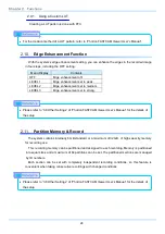
Page 37: ...e image emphasized D5 Gain 4x The gain is doubled and you can display the dark areas of the image emphasized This LUT emphasizes the dark portions even more than D4 D6 Reverse Gradation The input grad...

Page 38: ...r to 3 8 Other Settings of Photron FASTCAM Viewer User s Manual for the details of the setup 2 11 Partition Memory Record The system contains internally 8 GB standard or a maximum of 32 GB of high cap...

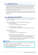
Page 39: ...to varies of customer s needs DIRECT TRIGGER Mode This mode is NOT supported on PFV software trigger START TRIGGER Mode Recording starts immediately upon the second trigger input CENTER END MANUAL TRI...

Page 40: ...l condition is limited as within a safe temperature The fan is operated forcibly when a camera is heated up And this function is disabled until the internal camera head temperature falls down to under...

Page 41: ...Chapter 3 Specifications 3 1 Specifications 3 2 Dimensions 27 FASTCAM Multi Camera Head HS 01...

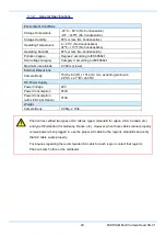
Page 42: ...max Lens Mount G type F mount C mount Micro Four Thirds mount Option Recording Bit Depth Monochrome 12bit Color RGB each 12bit Bayer color filter method Shutter Method Electronic shutter Recording Met...

Page 43: ...dy 70 H x 69 W x 151 4 D mm excluding protrusion 2 8 H x 2 7 W x6 0 D DC Power Supply Power Voltage 28V Power Consumption 25VA Power Consumption with LED Light Option 37VA Weight Camera Body 0 98kg 2...

Page 44: ...80 144 50 60 125 250 500 1 000 2 000 3 000 4 000 4 800 5 000 6 000 7 500 8 000 10 000 12 500 16 000 20 000 25 000 30 000 40 000 50 000 60 000 75 000 80 000 100 000 125 000 200 000 300 000 400 000 500...

Page 45: ...000 12 500 16 000 20 000 25 000 30 000 40 000 50 000 60 000 75 000 80 000 100 000 125 000 200 000 300 000 400 000 500 000 600 000 750 000 The mark indicates a possible setting The green items are the...

Page 46: ...0 000 12 500 16 000 20 000 25 000 30 000 40 000 50 000 60 000 75 000 80 000 100 000 125 000 200 000 300 000 400 000 500 000 600 000 750 000 The circle indicates a possible setting The green items are...

Page 47: ...000 4 000 60 000 625 000 4 800 62 500 750 000 5 000 75 000 The unit in the chart is 1 x sec At a frame rate 50 200 000fps a shutter speed of 1 frame sec or lower in the green area in the above table c...

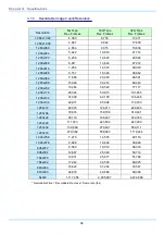
Page 48: ...x232 19 264 38 549 77 117 1 280x176 25 394 50 815 101 655 1 280x144 31 038 62 108 124 246 1 280x104 42 977 85 996 172 033 1 280x72 62 078 124 217 248 493 1 280x56 79 816 159 708 319 491 1 280x48 93 11...

Page 49: ...20 000 0 96 1 93 3 86 1 280x176 25 000 1 02 2 03 4 07 1 280x144 30 000 1 03 2 07 4 14 1 280x104 40 000 1 07 2 15 4 30 1 280x72 50 000 1 24 2 48 4 97 1 280x56 60 000 1 33 2 66 5 32 1 280x48 80 000 1 16...

Page 50: ...G type F mount 3 2 Dimensions 3 2 1 Camera Body mm 17 8 190 4 150 8 9 1 69 38 8 35 9 35 5 45 39 0 5 39 3 69 9 0 5 77 80 47 80 28 6 M3 DEPTH4 Caution If installing a longer screw than the specified de...

Page 51: ...59 8 45 8 38 8 48 86 8 0 5 9 1 69 32 8 17 8 28 60 35 5 45 35 9 38 8 190 4 150 9 4 M4 DEPTH6 4 5 DEPTH5 5 6 M3 DEPTH4 1 4 20UNC DEPTH6 3 8 16UNC DEPTH6 Caution If installing a longer screw than the sp...

Page 52: ...STCAM Multi Camera Head HS 01 C mount mm 161 3 150 8 9 1 69 10 0 5 69 9 39 3 0 5 77 80 47 80 17 8 28 6 M3 DEPTH4 Caution If installing a longer screw than the specified depth in mm its screw hole or t...

Page 53: ...3 2 2 Clearance for Camera Cable Connection Minimum 275 39 FASTCAM Multi Camera Head HS 01...

Page 54: ...Chapter 3 Specifications 40...

Page 55: ...Chapter 4 Warranty 4 1 About the Warranty 41 FASTCAM Multi Camera Head HS 01...

Page 56: ...other natural disasters pollution or the effects of abnormal voltage 2 Damage or malfunction as a result of dropping or mishandling during shipment or when moving after purchase or misuse 3 Consumable...

Page 57: ...Chapter 5 Contacting Photron 5 1 Contact Information 43 FASTCAM Multi Camera Head HS 01...

Page 58: ...nd Antipodes PHOTRON USA INC 9520 Padgett Street Suite 110 San Diego CA 92126 4426 USA Phone 800 585 2129 or 858 684 3555 Fax 858 684 3558 E mail image photron com www photron com In Europe Africa and...

Page 59: ...ontrol No E150609U 2 F FA AS ST TC CA AM M M Mu ul lt ti i C Ca am me er ra a H He ea ad d H HS S 0 01 1 Hardware Manual Revision 1 01E Publication Date June 2015 Publisher PHOTRON LIMITED 21F Jimboch...

Reviews: