background image

14


3 .   E T H E R N E T   P A G E  

E t h e r n e t   >   D o w n l i n k   P o r t s  


P h y b r i d g e   N V T   P o L R E   S w i t c h   U s e r   G u i d e  


Ports 1-24 and Ports 25-48 

Used to manage the downlink ports. 

Viewing dongle information 

Dongle summary information is shown above the port details table and includes the number of dongles 

connected, the number of endpoints connected to the dongles, the total power being consumed, and the 

temperature of the switch. This information is updated in real-time. 

Viewing port information 

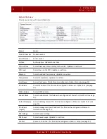
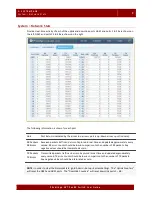
The following information is shown for each port.   
Double click a port number to bring up link transition statistics for that specific port. 

Summary of Contents for NVT PoLRE Series

Page 1: ...PoLRE Switch User Guide Version 3 1 5...

Page 2: ...c Chrome is a trademark of Google Inc Firefox is a registered trademark of Mozilla Inc Phybridge Inc Corporate Headquarters 2115 South Service Road West Oakville ON L6L 5W2 Canada www phybridge com NV...

Page 3: ...re Celsius 8 System Network Stats 9 3 Ethernet Page 11 About the Ethernet Page 11 Ethernet Uplink Ports 11 Configure GbE Interface 12 Configure Management Port 12 Configure IP Route 13 Ethernet Downli...

Page 4: ...31 Spanning Tree Protocol 31 Simple Network Management Protocol 32 Admin Log 32 Selecting the number of events to display 33 Searching Log entries 33 Adding markers to the log 33 Downloading the log...

Page 5: ...also includes a command line interface for managing the switch The Simple Network Manager is divided into five main pages System Provides an overview of the system key system statistics and control of...

Page 6: ...refox 2 Enter the IP address of the switch in the address bar The default IP address of the switch is 192 168 100 1 3 Enter admin as the username 4 Enter the password the default password is admin Man...

Page 7: ...dge NVT P oLRE Switc h User Guide 2 System Page About the System Page The System page provides high level switch details allowing you to monitor and control the system The System page contains three t...

Page 8: ...st Name Current host name This field can be configured in Admin Setup see page 25 IP Address Current IP address This field can be configured in Ethernet Uplink Ports see page 11 MAC Address Current MA...

Page 9: ...colour of the port number and port box Colour Port Status Black text grey box Port is available with power nothing is attached to the port Red text grey box Port power is disabled Black text blue box...

Page 10: ...ors such as CPU load memory power consumption and temperature The date and time is shown for each indicator and the information is updated in real time System Performance All panels provide current va...

Page 11: ...istently above 1 0 Graph provides an overview of the historical CPU load Memory Megabytes Legend shows the current memory usage allowing you to visualize available memory Graph provides an overview of...

Page 12: ...h and all devices connected to it Expect variations as activities on the switch change Peaks and valleys are normal as devices are added and removed Temperature Celsius Legend shows the current switch...

Page 13: ...ackets traffic and errors Captured in real time and updated approximately every second RX error counts should be low in comparison to the number of RX packets Any negative values should be interpreted...

Page 14: ...10 2 S YS TEM P AGE Syst e m Net work St at s P hybridge NVT P oLRE Switc h User Guide...

Page 15: ...Ethernet Page The Ethernet page allows you to configure the switch network interface and manage uplink and downlink ports The Ethernet page contains two tabs Uplink Ports Downlink Ports Ethernet Upli...

Page 16: ...will be required to log back into the box The management port IP address and the uplink port IP address should never be on the same subnet This ensures the management port can still be reached if the...

Page 17: ...the default gateway IP address and to select the interface to apply it to 1 Modify any of the fields Default Gateway Interface Notes The Default Gateway can be assigned to only one interface The inter...

Page 18: ...on is shown above the port details table and includes the number of dongles connected the number of endpoints connected to the dongles the total power being consumed and the temperature of the switch...

Page 19: ...orts at once MAC Address MAC address of the IP device connected to the dongle associated with this port UPTIME Amount of time a device has been connected to the dongle LD Number of link down events th...

Page 20: ...16 3 ETHERNET P AGE Eth er ne t D ownlin k P ort s P hybridge NVT P oLRE Switc h User Guide...

Page 21: ...o PORT ASSIGN PVID VLAN VLAN Table Use to add or delete a VLAN or to change the default VLAN For each VLAN the VLAN number type and ports are shown IMPORTANT Do not use VLAN 0 There is potential in th...

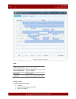
Page 22: ...er Guide NOTE WHITE BACKGROUND Port is not a member BLUE BACKGROUND Port is a member BLACK TEXT Port is a PVID GREY TEXT Port is only a member of the VLAN Adding a VLAN You can add a new static VLAN 1...

Page 23: ...ORT tab appears with the VLAN panel open You can now assign ports to the VLAN see VLAN VLAN To Port on page 19 Setting the default VLAN The default VLAN is used for ports not assigned to any other VLA...

Page 24: ...HANGES any changes made on this tab will be lost after a system reboot Viewing VLAN port details Each VLAN is shown as a separate panel 1 Click the panel header the VLAN number to expand the panel 2 A...

Page 25: ...ne or more ports in the VLAN panel or Click ALL to select all ports Click NONE to clear all ports A checkmark is shown on selected ports 2 Click REMOVE The removed ports now have a white background 3...

Page 26: ...VID Use to assign the primary VLAN ID to ports VLANs created in the VLAN Table tab can be used for PVID tagging For details on adding and removing VLANs see VLAN VLAN Table on page 17 IMPORTANT If you...

Page 27: ...und Ports that do not belong to the PVID have a white background Adding or modifying a port PVID IMPORTANT The switch may lose connectivity if you change the PVID of the GbE ports Use caution when con...

Page 28: ...24 4 VLAN P AGE V LA N As sign PV ID P hybridge NVT P oLRE Switc h User Guide...

Page 29: ...h User Guide 5 Admin Page About the Admin Page The Admin page allows you to configure switch settings control services configure servers view the switch event log and use the command line interface T...

Page 30: ...48 56V use slider to adjust Click APPLY Admin Password Confirm Password Simple Network Manager password To change the password enter the new password in both of these fields NOTE You will be prompted...

Page 31: ...from 2 When the file download is complete the file should be shown in the bottom left corner of your browser Chrome or in the Downloads window Firefox Double click the file to open it 3 You can modify...

Page 32: ...User ID Password Enter only if required If User ID and Password had been set up Click CONNECT Select Package to Install You can selectively install any package that is available Click INSTALL NOTE Pr...

Page 33: ...5 ADMIN P AGE Ad mi n Ser vi ces 29 P hybridge NVT P oLRE Switc h User Guide Admin Services...

Page 34: ...you disable the HTTP service the Simple Network Manager will not function after a reboot If you stop the HTTP service you will instantly lose connectivity to the Simple Network Manager Run Click to st...

Page 35: ...tch Protocol button The button name changes based on the currently selected protocol For example if the current protocol is RSTP the option Switch Protocol from RSTP to STP will be shown 2 To change t...

Page 36: ...to modify the simple network management protocol 1 To change the receiver IP address enter the address and click APPLY 2 To enable disable the receiver click the Enable Receiver checkbox Admin Log Use...

Page 37: ...s in the Log entries containing window Search terms are case sensitive and spaces are significant 2 Click SEARCH The Log tab is updated immediately 3 Search results are shown in green text and the log...

Page 38: ...ted file uses the convention hostname log example switch log This allows you to easily identify which switch the file was exported from NOTE You can continue using the Simple Network Manager while the...

Page 39: ...5 P hybridge NVT P oLRE Switc h User Guide Admin Terminal The Terminal tab provides you with a command line interface you can use to configure the switch and diagnose switch issues You can also use th...

Page 40: ...click in the results area to view editing options such as copy paste and spell check Click SAVE to save the results in a text file When the file download is complete the file should be shown in the b...

Page 41: ...message stating that the values are not within the acceptable range Command Purpose Usage Usage Notes pal Main interface for PAL pal help cmd short long configure examine persistent pal conf edit Mod...

Page 42: ...e on the switch pal service ntp start stop restart enable disable pal service snmp Enable or disable SNMP service on the switch pal service snmp start stop restart enable disable pal service snmp rece...

Page 43: ...mal operation pal set contact Update the point of contact for the switch pal set contact CONTACT CONTACT is a single value entry of the person s name that will be the point of contact for the switch p...

Page 44: ...mp contact STRING STRING can not contain special characters pal set staticmac Lock MAC addresses to specific ports pal set staticmac unlock 1 48 all pal set staticmac lock 1 48 MAC VLAN pal set static...

Page 45: ...n only be assigned to 1 interface at a time pal set sys hostname Set the hostname of the switch Note that the following special characters are not supported pal set sys hostname HOSTNAME HOSTNAME is a...

Page 46: ...ppropriate choice pal set vlan Create and delete VLANs on the switch pal set vlan create VLANID pal set vlan delete VLANID pal set vlan default VLANID pal set vlan clear VLANID is a single value entry...

Page 47: ...figure This value ranges from 1 24 on a 24 Port switch and 1 48 on a 48 Port switch pal show port statistics Show port statistics pal show port statistics RANGE RANGE is a single value entry of a port...

Page 48: ...mac Show port MAC lock status pal show staticmac 1 48 all pal show sys date Show the system date and time pal show sys date pal show sys gateway Get the gateway of the switch and which port it is boun...

Page 49: ...ge Notes pal show vlan default Show the default VLAN s configuration pal show vlan default 1 48 all system 1 48 and all are port defaults where system is the system default pal show voltage Show the d...

Page 50: ...an upgrade For details see Admin Setup on page 25 Command Purpose Usage Usage Notes pal pkg Used to upgrade remove and show the installed software packages on the switch pal pkg show_remote show_inst...

Page 51: ...line on the Admin Terminal tab configure the package upgrade utility to point it to the upgrade server and subfolder This is done with the pal pkg command with the configure option pal pkg configure U...

Page 52: ...es are done using the incremental method In case of problems the following instructions can be followed NOTE Holding down the reset button during the bootup process will reset the unit to the default...

Reviews: