background image

12


1 .   P R O D U C T

  D E S C R I P T I O N  

P h y l i n k   A d a p t e r   H a r d w a r e   D e s c r i p t i o n  


Phylink Dimensions 


Height: 1.8cm (0.71”) 


Width: 2.8cm (1.1”) 


Depth: 6.5cm (2.56”) 


Weight: 22 g (0.78 oz.) 

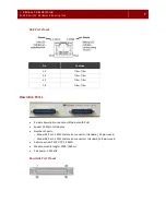
Network Infrastructure Connector 


RJ11 port 


Connects to the single CAT3 pair on the legacy infrastructure side 

Ethernet Connector 


RJ45 port 


Provides connectivity and power to the IP end device. 


DC voltage -54V max; -37V when 365m (1200’) away from the PoLRE switch 


Speed: Fixed 10 Mb/s Full Duplex Auto-MDIX 


Cable: CAT-5 or better 


Summary of Contents for PoLRE

Page 1: ...PoLRE Switch Hardware Installation Guide Release 1 2...

Page 2: ...kes no warranties regarding the content of this document Phybridge is not responsible for any loss or damages arising from the use or misuse of this document The information contained in this document...

Page 3: ...umber and password ready when calling Returning a PoLRE Switch If you must return a PoLRE switch Phylink adapter or accessory component to Phybridge Inc ensure that all items are adequately protected...

Page 4: ...netic field or electrostatic charge Damage to system components could result Warnings A warning contains an instruction that the reader must follow in order to prevent electrical shock death or seriou...

Page 5: ...link Ports 6 GbE Port Pinout 7 Downlink Ports 7 Downlink Port Pinout 7 Ports 1 to 24 8 Ports 25 to 48 8 Out of band Management Port 8 Out of band Management Port Pinout 9 Console Port 9 Reset Button 1...

Page 6: ...ith IP Endpoint Devices 23 Connecting a PC Behind the IP Phone 24 Connecting to the 2 wire Network Infrastructure 24 Connecting to the Console 26 Connecting to the IP PBX 26 GbE Port Connection 27 Gbi...

Page 7: ...odels 24 Port and 48 Port page 3 PoLRE Switch Rear View Models 24 Port and 48 Port page 4 Power Supply Unit page 5 Uplink Ports page 6 Downlink Ports page 7 Out of band Management Port page 8 Console...

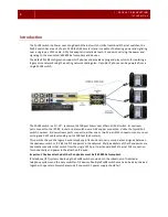
Page 8: ...he IP PBX router or data switch over a GbE copper connection Unlike the typical PoE switch however its downstream ports connect to either one or two 25 pair RJ21 connectors and run over voice grade CA...

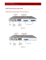
Page 9: ...1 P RO DUCT DES CRIP TION P oLRE S wi tc h Har d war e Descri pt i on 3 PoLRE Switch Hardware Description PoLRE Switch Front View Models 24 Port and 48 Port Model 48 Port Model 24 Port...

Page 10: ...switch indicates the generic model number 24 Ports or 48 Ports The product serial number as well as the switch specific model number are on a label affixed to the left side of the rear panel You may...

Page 11: ...onnector at the rear Autosensing 100 240VAC 50 60 Hz 2 male DC connectors In Out at the rear of the unit for Powershare 54VDC nominal 42VDC to 58VDC tolerance Power output 500W max at 100VAC 1000W max...

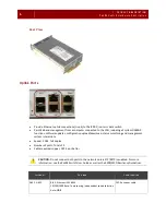
Page 12: ...tion upload download status monitoring and management system interactions Speed 1 GbE full duplex Number of ports Total of 2 Cable required copper CAT 5e or better CAUTION Do not connect both ports to...

Page 13: ...T Rx T Rx Downlink Ports Provide downlink connections Ethernet with PoE Speed 10 Mb s full duplex Number of ports Model 24 Port 1 RJ21 male telco connector standard 24 pairs used Model 48 Port 2 RJ21...

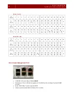
Page 14: ...25 to 48 PIN Number 1 2 3 4 5 6 7 8 18 19 20 21 22 23 24 25 Port Number TR 25 TR 26 TR 27 TR 28 TR 29 TR 30 TR 31 TR 32 TR 42 TR 43 TR 44 TR 45 TR 46 TR 47 TR 48 X PIN Number 26 27 28 29 30 31 32 33...

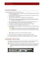
Page 15: ...t Pin Function 1 TX 2 TX 3 RX 4 5 Bob Smith Termination 6 Rx 7 8 Bob Smith Termination Console Port 1 RJ45 UART port labeled Console Dedicated port for management of the PoLRE switch via a console ter...

Page 16: ...abeled Reset for manually restarting the PoLRE switch Located on the front panel of the PoLRE switch immediately to the right of the power supply unit Use a paper clip or something similar to press th...

Page 17: ...rtup then turns off Lights solid to indicate a problem with the PSU FAULT red Flashes once during startup then turns off Lights solid to indicate a PoLRE switch software or hardware failure Contact Ph...

Page 18: ...56 Weight 22 g 0 78 oz Network Infrastructure Connector RJ11 port Connects to the single CAT3 pair on the legacy infrastructure side Ethernet Connector RJ45 port Provides connectivity and power to the...

Page 19: ...t 1 console cable 1 power cord Other PoLRE components are packaged separately for installation in the field Verify that you have received all of the items you ordered Phylink adapters The number of ad...

Page 20: ...f supporting the size and weight of the PoLRE switch its installable components and cabling Refer to PoLRE Switch Dimensions page 4 Ensure that you have enough rack space for all equipment Shelves and...

Page 21: ...he CONSOLE port provided with the product package Standard CAT 5 or CAT 6 Ethernet LAN cable for the MGMT port user supplied DC cables for multiple switch configuration in Powershare mode optional Scr...

Page 22: ...16 2 U NP AC KI NG Before Y ou I ns tall...

Page 23: ...acing Legacy Devices with IP Endpoint Devices page 23 Connecting a PC Behind the IP Phone page 24 Connecting to the 2 wire Network Infrastructure page 24 Connecting to the Console page 26 Connecting t...

Page 24: ...is CAUTION When upgrading a telephony environment make sure you have removed all of the old analog digital phones and fax machines before you apply power CAUTION To ensure trouble free synchronization...

Page 25: ...ist einer der wichtigsten Erdungsklemme die dauerhaft auf die Erde angeschlossen werden muss Seul un sp cialiste doit avoir acc s l appareil Cette unit peut avoir plus d une entr e d alimentation Pour...

Page 26: ...be used on the components of the PoLRE switch or applied to the interior of the switch Care of Replaceable Components CAUTION Handle replacement components with care Do not drop them Do not spill liqu...

Page 27: ...ole cable See Connecting to the Console page 26 7 Connect the uplink cable from a Gigabit port to the IP PBX or network switch See Connecting to the IP PBX page 26 CAUTION Do not connect both ports to...

Page 28: ...nit This handle is intended for removing and replacing the PSU only 3 Slide the PoLRE switch into the rack along its horizontal supports or suspend the switch in place using another means of support s...

Page 29: ...ratings should be used when addressing this concern For reliability reasons the PoLRE switch should be powered from a dedicated mains outlet Reliable Earthing Reliable earthing of rack mounted equipm...

Page 30: ...establish VLANs to ensure Quality of Service For more information on how to set up VLANs see the PoLRE Switch User Guide Note Data speeds are 10 Mb s Full Duplex Connecting to the 2 wire Network Infr...

Page 31: ...to a downlink port Tip If you are installing only one RJ21 telco cable on a model 48 Port either downlink port can be used However for easier reference to port numbering use the connector on the left...

Page 32: ...uter must be running at 115 200 baud with 8 data bits no parity and 1 stop bit Connecting to the IP PBX You can connect the PoLRE switch to the uplink network switch IP PBX or router in two ways GbE P...

Page 33: ...P RSTP is enabled For more information see the PoLRE Switch User Guide as well as the 3300 MCD Resiliency Guidelines Note Both ports can be used If only one connection will be installed use the port l...

Page 34: ...pulling it down over the black cap When open it can be used as a handle for inserting or removing the SFP module 3 Determine which Gbic port will be installed with this SFP module For the upper port...

Page 35: ...the SFP module 2 Unlock the SPF module If the SFP module is in port Gbic 1 flip the handle down to unlock the module If the SFP module is in port Gbic 2 flip the handle up 3 If required remove the pr...

Page 36: ...Remove the black protective cap from the SFP transceiver module WARNING DO NOT look into the SFP connector when it is installed in a Gbic port as the laser beam can cause serious eye injury 2 Connect...

Page 37: ...his requires multiple PoLRE switches installed in a standard 19 equipment rack For details refer to Daisy chaining PoLRE Switches for Powershare page 32 AC Connection To connect the PoLRE switch to an...

Page 38: ...nected in a ring using the DC In Out connectors at the rear of the switch If a power fault occurs on any switch in the ring the others are able to share the load and the affected switch continues to f...

Page 39: ...uipment rack with no more than 1U space between any two switches Refer to Installing the Switch in a Rack page 21 Note You can daisy chain the switches together while they are up and running or power...

Page 40: ...switch press the hairpin clip at the top of the DC cable and pull the cable out Replacing the Power Supply Unit If a power supply unit fails you must replace it with a new power supply unit as soon a...

Page 41: ...with the handle on the right side 2 Lift the new power supply unit by its handle and slide it straight into the PSU housing on the left side of the PoLRE switch 3 Push firmly on the power supply unit...

Page 42: ...apter Model 24 Port 1 RJ21 male telco connector standard 24 pairs used Model 48 Port 2 RJ21 male telco connectors standard 48 pairs used Maximum distance 1200 365m CAT3 UTP cable 24 AWG Speed 10Mb s f...

Page 43: ...D Weight 22 g 0 78 oz Enclosure ABS AF 312B Mounting Inline between the CAT5e cable to IP endpoint and the CAT3 cable to RJ11 jack Interfaces PoLRE side 1 RJ11 port CAT3 unshielded single twisted pair...

Page 44: ...5 CO MP LIANCE AND ENVIRO NMENTAL INFO RMATIO N 38 5 Compliance and Environmental information All the compliance and environmental information is available on our website www phybridge com...

Page 45: ...ernet Protocol IPT IP Telephony LED Light Emitting Diode NMS Network Management System OAM P Operations Administration Maintenance and Provisioning PoE Power over Ethernet PoLRE Power over Long Reach...

Page 46: ...40 6 ACRO NYMS...

Page 47: ...itch 5 ESD procedure 18 Ethernet port PoLRE switch 12 FAULT LED 11 fiber optic cable 29 front panel 3 GbE port connection 26 Gbic port connection 26 ground lug 18 installation 17 2 wire network connec...

Page 48: ...cators 11 Powershare 31 product numbers Phylink adapter 11 PoLRE switch 4 product package 13 rackmount installation 20 safety warnings 22 rear panel 4 redundancy Powershare 31 removal SFP module 28 re...

Page 49: ...2115 South Service Road West Oakville ON L6L 5W2 Canada Tel 1 888 901 3633 Fax 1 866 252 9148 Web www phybridge com...

Reviews: