4. With power disconnected, connect the high voltage cable (not
supplied) to the ion pump and to one of the high voltage jacks on
the rear panel (Figure 2-1 ).
Note
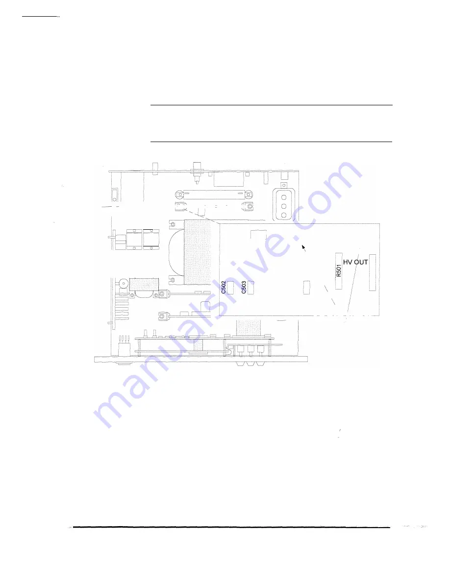
For negative output operation, the polarity must be changed. To
do this, reverse the position of wires E501 and E502 on the high
voltage (HV) board and solder them (Figure 2-2).
High - ---- ---����---/:2J..!C==;c=cc�===,
Voltage
Board
J501'
E503
--A\/ RET
E502
HVIN
E�01
E504
Top View of Chassis
High Voltage Boa�,
�
\
§
\
\
----�-\ :---��-
\/
Location of wires
E501 and E502 on the
HV board.
Figure 2-2. Location ofE501 and E502 on HV Board
5. Connect the detachable power cord to input power on the rear
panel and plug it into the wall.
6. Tum the unit on and verify the operation as described in Section 3.
Installation
2-3


