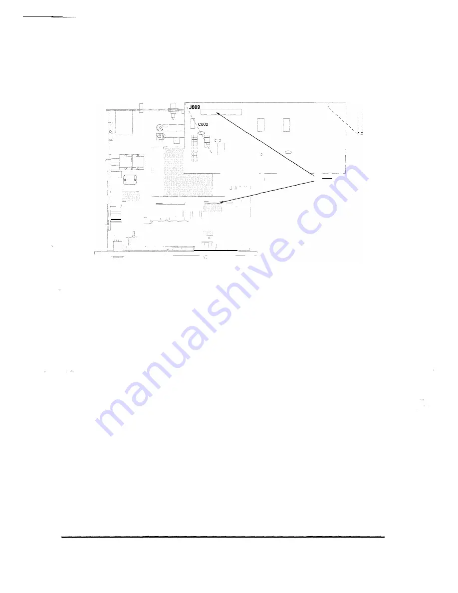
6. Put the ribbon cable in the guides on the left side of the chassis.
Baud Jumper
:-�!
9600
• • 4800
• ., 2400
• •i 1200
• • 600
300
Computer Interface Option Board
s
r1
I i�,i�_:_ :, ,:�.,.-�---� , ... -
u -��
�
,_L;
,,., -
!b::�)�
'1 � '
t
©=
\:
LS)
•
: l'§c£�
'-"-
� -
�c==--=-==---=;--- ,� ::I� Install Computer Interface
, =
,----,,-----,
r-----"
Option Board here
1 F=i
-= - __
I _
--� _
�
,
(longer ribbon cable shown).
-�
�--- -- -�-� J709 on Setpoint Option Board
_J:D __ TopView ofChassis =k
==
�
c;:;==c===�--_c:•--�
-2.i�-�-
�
=
:
J109 on CPU Board
�--=-====- -
- -
�_-r:::rc:r-��-'
After you have
finished
2-8
Installation
Figure 2-7. Installing the Computer Interface Board
7.
Installing the Computer Option only.
Attach the 2-position,
ribbon cable connector into J109 on the CPU board and 1809 on
the computer interface board with the colored stripe (pin 1) closest
to the left side of the chassis when facing the rear panel.
Installing the Computer Option with the Setpoint Option
installed.
If the 2-position short ribbon cable is installed on the
setpoint board discard it. Plug the 3-position longer ribbon cable
(supplied with the computer interface option) into J109 on the CPU
board, 1709 on the setpoint board, and 1809 on the computer
interface board (Figure 2-7). Pin 1 should be closest to the left side
of the chassis when facing the rear panel.
Make sure all boards and connectors are seated properly. Replace
cover with slotted holes toward front of unit. Replace six mounting
screws.


