7. Push the
POWER
switch to on (flush with the bezel).
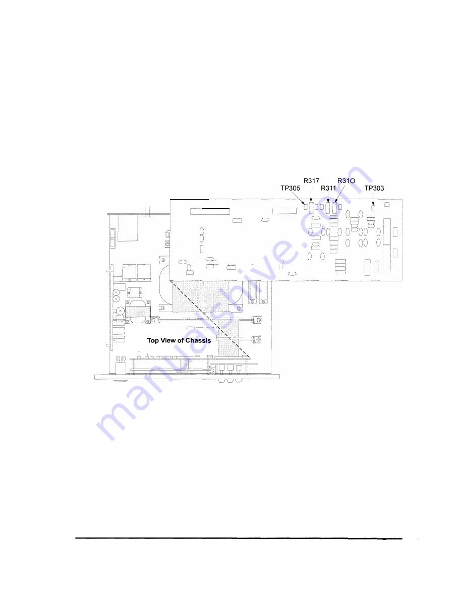
8. Connect a voltmeter between TP305 and TP303 (ground) on the
CPU board to check the voltage reference. If necessary, adjust
R317 to obtain a DVM reading of-3.06V (Figure 4-3).
Disconnect the DVM.
9. Press the
CURR 5
key to enter the current display mode.
10. Check the zero adjustment. If necessary, adjust R311 so that the
front panel display reads 0.0 x 10-
5
.
J109
c:)
c:)
c:)
CPU Board
!\,
V
Figure 4-3. CPU Board Calibration Components
11. Disconnect the power cable from the rear of the unit.
Service
4-5


