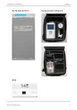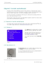
2.1.3 Ports <3>
Ports <3>
The
Ports <3>
serve to connect the supplied cables for the hand applic-
ator and the adhesive or neutral electrode with the instrument.
You can find instructions on how to connect the cables in section
on page 15.
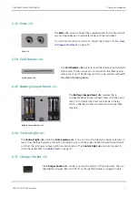
2.1.4 Card Reader <4>
Card Reader <4>
The
Card Reader <4>
serves to insert the therapy card which en-
ables access to the user menus, and on which the therapy para-
meters are stored. The therapy card has to be inserted with
with
the chip side facing down
.
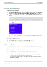
2.1.5 Battery Compartment <5>
Battery Compartment <5>
The
Battery Compartment <5>
receives the re-
chargeable batteries and connects them with the instru-
ment. It is protected by a rear cover made of metal,
which is attached to the instruments housing by three
magnets.
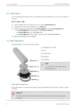
2.1.6 Control Light <6>
The
Control Light <6>
under the
Data Selector <2>
is on as soon as the intensity is being increased. In
case of low therapy frequency, the light is flashing in sync with the pulses. When the electrostatic field is
cut short, the light goes out even with non-zero intensity. The
Control Light <6>
can also be used to
check the cables (refer to
on page 12).
2.1.7 Charger Socket <7>
The
Charger Socket <7>
can be found on the bottom of the instrument. The sup-
plied battery charger (Ref.-No. 00277) to charge the batteries is plugged in here.
PHYSIOMED ELEKTROMEDIZIN AG
2 Controls and Indicators
DEEP OSCILLATION
®
Personal
7


