background image

Individual Programs 


42  

IONOSON-IF-Expert 

8.3


Call Program 

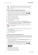
To call a saved program proceed as follows: 

(1)


Select the menu 

INDIVID

 from the 

display <3>

(2)


Select one of the programs 

F1

 to 

F25

 using the 

data selector <5>

 and confirm. 

(3)


Select the symbol 

call program


 and confirm. 

The selected program is set. The respective menu appears in the 

display <3>


The program number appears in the 

lower status bar <4>

 (e.g. 

F3

) and, in case of 

a potpourri, additional indicator dots showing the position within the potpourri are 
displayed. The number of dots corresponds to the position number in the potpourri; 
on the display above, e.g. the momentary mode of treatment is carried out using 
current no. 1 in program F3. 

Using a single therapy mode, you are only shown the program number. 


Note 


When selecting a current sequence, you always have to reset the in-
tensity after every current mode before you can apply the next current 
mode. This measure enhances the protection of the patient. 

8.4


Delete Program 

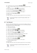
Proceed as follows to delete a program:  

(1)


Select a current mode on the 

display <3>

(2)


Select the symbol p

rograms


. The menu 

individual programs

 will be 

displayed. 

(3)


Select one of the programs 

F1

 to 

F25

 with the 

data selector <5>

 and confirm. 

(4)


Select the symbol 

delete programs

. The bin symbol starts flashing. 


(5)


Select the program to be deleted and confirm. 

(6)


Exit the menu. 

Now the program is deleted and can be newly assigned. 

Summary of Contents for IONOSON-IF-Expert

Page 1: ...00906 GB O P E R A T I N G I N S T R U C T I O N S IONOSON IF Expert...

Page 2: ...and subject to alteration Copyright 2001 2010 by PHYSIOMED ELEKTROMEDIZIN AG All rights including rights of translation reproduction by printing copying or similar methods even of parts are reserved O...

Page 3: ...ontrol Circuit II Dose 13 Ultrasonic Transducer Connector 4 Lower Status Bar 9 Pulse Indicator Circuit II 14 Manual Release Key or Therapy Pause Button Socket 5 Data Selector 10 Patient Current Indica...

Page 4: ......

Page 5: ...Circuit I 10 2 3 2 Dual channel operation 13 2 3 3 Parameters for Circuit II Ultrasound 15 2 4 Characterisation of the Individual Current Modes 16 2 4 1 Low frequency Current Modes LF 16 2 4 2 Medium...

Page 6: ...tment Procedures using Ultrasound 38 8 Individual Programs 40 8 1 Save Individual Therapy Modes 40 8 2 Save Potpourri 41 8 3 Call Program 42 8 4 Delete Program 42 9 Basic Settings 43 9 1 Stimulation C...

Page 7: ...t may be accessed directly or by a proposed treatment via the indications menu page 37 Moreover the unit enables you to memorise up to 25 individual treatment programs or current sequences potpourris...

Page 8: ...rts within the area of treatment Contraindications to ultrasound therapy or simultaneous treatment Fever prone disorders and acute inflammatory processes Pregnancy Tuberculosis gastric ulcers Vascular...

Page 9: ...rview at the be ginning of this manual 2 1 1 Mains Module 1 The mains module 1 with mains supply fuses and mains switch is situated at the rear side of the instrument For mains supply do only use the...

Page 10: ...pa rameters and to operate the instrument by means of the cursor After switching on the instrument the cursor is located at the current mode G of the dis play 3 You can move the cursor to the other me...

Page 11: ...the previously set value and the message will disap pear 2 1 7 Pulse Indicator Circuit I 7 The pulse indicator circuit I 7 serves to visually monitor the cur rent modes and intensities of circuit I It...

Page 12: ...sity control circuit II dose 8 the indicator will start flashing again Note Due to safety reasons increasing the ultrasound dose after the ultra sound has coupled marker appears in the upper status ba...

Page 13: ...e ground wire Warning Take care that the electrodes are by no means touched after the cur rent is turned up 2 1 13 Ultrasonic Transducer Connector 13 The ultrasonic transducer is connected to the inst...

Page 14: ...nsducer is not dropped Handling malpractice can change the physical characteristics of the transducer 2 1 14 Manual Release Key Socket 14 The manual release key socket 14 serves to connect a manual re...

Page 15: ...s bar 2 setup menu individual programs freely configurable lower status bar 4 current modes direct access ultrasound menu direct access therapy timers circuits I II current mode parameters circuit I b...

Page 16: ...sed via plate electrodes switching is slightly de layed Setup menu settings Back to level 1 Therapy timer with selected therapy time the therapy current will be reduced to 0 and an acoustic signal wil...

Page 17: ...alues OFF 1 10 Hz Frequency bands 70 150 Hz or 1 150 Hz or fixed frequency 1 200 Hz Note When selecting an additional therapy mode in circuit II the pulse time is limited to 300 s for HV and TENS If y...

Page 18: ...ntrol I 6 Tension time possible values 1 to 60 s in steps of 1s manual release key only if R 1s Release time possible values 1 to 60 s in steps of 1s Ramp 4 settings m1 to m4 with different rise times...

Page 19: ...With the data selector 5 first click on the selection field and turn the selector to the left until the desired icon appears e g for simultaneous stimulation The parameter R will acquire the appropri...

Page 20: ...both circuits then simultaneous stimu lation will also follow Alternating stimulation continuous transition between circuits I and II Circuits I and II provide alternating stimulation one directly af...

Page 21: ...set the following parameters Intensity control dose from 0 1 to 5 7 W cm2 in steps of 0 1 W cm2 adjustable with intensity control II dose 8 Mode of treatment adjustable parameters are 1 10 1 5 1 3 2...

Page 22: ...Direct current without any interruption or break Variation Medium frequency interrupted direct current 8 kHz duty cycle 95 Application Iontophoresis basic therapy for paralysis and atrophy treatment...

Page 23: ...hase Application Pain therapy for chronic neuralgia and myalgia 2 4 2 Medium Frequency Currents IF Classic Interference Current Fixed parameters Adjustable Sinusoidal waves Vector function dynamic fun...

Page 24: ...z 100 250 Hz or any other Select fixed frequency 0 250 Hz Application According to choice of parameters pain therapy circulatory stimulation detonisation a o MT Medium Frequency Muscle Training Fixed...

Page 25: ...action 1 60 s manual triggering manual release key R release time between contractions 0 60 s T pulse time 2 ms 4 ms 6 ms 8 ms 10 ms auto Pulse shape sine triangle rectangle R release time 10 ms Ramp...

Page 26: ...control circuit I 6 and intensity control circuit II dose 8 to 0 3 Plug the patient lead into the patient lead connector 12 4 Switch on the device with the mains switch mains module 1 The instrument...

Page 27: ...e g ERROR 10 The instrument will be switched off stimulation cur rent output is cut off as well The LCD shows These error codes simplify localising and eliminating errors Switch off the instrument an...

Page 28: ...treatment proposals for a multitude of applications page 37 starting via individual programs created by yourself page 32 4 2 Safety Precautions when Attaching Electrodes Please observe the following...

Page 29: ...ion when using current forms with a high galvanic compo nent G that the recommended intensity of 0 1 mA cm2 of active electrode sur face area is not exceeded If you use electrodes of various different...

Page 30: ...but as large as possible A larger electrode area usually makes treatment for the patients more pleasant 6 Plug the plate electrodes into the well moistened electrode covers and attach them to the pati...

Page 31: ...rity of low frequency current modes for pain therapy circulatory stimula tion detonisation and mobilisation can be applied in their basic monophase as well as biphase mode If this option exists the fo...

Page 32: ...de 3 Fix the electrode to the point of treatment Moisten the viscose cover of the op posite electrode sufficiently with water and fix it as well 4 Select the current mode G from the display 3 Watch fo...

Page 33: ...lation points 2 Select one of the above mentioned current modes from the display 3 e g TENS 3 Select the variable parameters e g frequency biphase etc 4 Set the therapy time 5 If necessary plug in the...

Page 34: ...the therapy time 7 If necessary plug in the manual release key as therapy pause button 8 Slowly turn up the intensity in circuit I with the intensity control circuit I 6 The therapy time elapses Warn...

Page 35: ...release key as therapy pause button 7 Slowly turn up the intensity of the respective circuit intensity control circuit I 6 or intensity control circuit II dose 8 The therapy time elapses Warning Take...

Page 36: ...ng Take care that the electrodes are by no means touched after the cur rent is turned up 11 Signs of fatigue should stop the treatment they may already occur after a few muscle contractions 12 After t...

Page 37: ...t at will increase auto matically and will keep the set intensity as long as the manual release key is pressed After releasing the button the intensity will automatically be reduced in intervals 12 Si...

Page 38: ...t the desired transducer and plug it into the ultrasonic head connector 13 3 Apply the ultrasound gel on the area of treatment 4 Select the therapy time unless a stimulation current therapy is already...

Page 39: ...patient s tis sue light at the transducer goes out Warning Make sure you constantly keep moving the transducer on the skin of the patient dynamic treatment Avoid using the transducer at one spot for a...

Page 40: ...cer is being coupled to the tissue refer to Ultrasound Therapy on page 32 The individual parameters one after the other have the following significance selected dose Refer to the Treatment Recommenda...

Page 41: ...tween the plate electrode and the trans ducer If there is too little room an error might be issued To ensure a stable contact for both stimulation and ultrasound therapy you must use an electrically c...

Page 42: ...nt therapy If the ultrasonic waves are badly absorbed by the tissue of the patient the light at the transducer will start flashing Now you can choose be tween counting the effective therapy time or ru...

Page 43: ...red indication from the indications menu Treatments with stimulation current do not contain the abbreviation US e g Lumbar spine syndrome The proposed parameters for the selected indication are displa...

Page 44: ...e care that the electrodes are by no means touched after the cur rent is turned up 9 After treatment an acoustic signal will be issued Turn the intensity down to 0 10 Remove the electrodes 7 2 Treatme...

Page 45: ...ensity down to 0 Automatic Coupling Confirmation The optical coupling confirmation at both transducer and instrument enables a sta ble and efficient therapy If the ultrasonic waves are badly absorbed...

Page 46: ...i There is an extra menu for the individual programs containing the following but tons 8 1 Save Individual Therapy Modes You can save individual programs only from one current mode You can either save...

Page 47: ...ree cur rent modes which can be retrieved individually You can save individual programs for only one current mode Proceed as follows 1 Select one current mode 2 Set the desired parameters 3 Select the...

Page 48: ...lay above e g the momentary mode of treatment is carried out using current no 1 in program F3 Using a single therapy mode you are only shown the program number Note When selecting a current sequence y...

Page 49: ...meaning Screen contrast Active menu when switching on the instrument e g START MENU Active menu when switching on the device START MENU means that the start menu will appear With LAST CURRENT MODE the...

Page 50: ...tion of coupling confirmation and timer YES timer runs only with successful coupling NO timer runs independently of coupling Back to the basic settings for stimulation current Quit basic settings To a...

Page 51: ...eter proceed as follows 1 Press the icon SET in any menu 2 Select the desired parameter with the data selector and confirm 3 Set the desired value of the parameter Modifications can be recognised imme...

Page 52: ...high frequency surgical instrument simultaneously since burns under the electrodes could be caused Operating the instrument in the vicinity e g 1 m of a short wave or micro wave therapy unit may cause...

Page 53: ...ansducer contains a fragile ceramic piezo resonator Avoid shocks to the surface and take special care that the transducer is not dropped Handling malpractice can change the physical characteristics of...

Page 54: ...A at 115 V Power line input 86 VA Line fuses at 230 V T 500 mA at 115 V T 1 A Output data STIMULATION 75 mAs peak at 500 Ohm Output data SONO small transducer large transducer Efficient surface 2 5 cm...

Page 55: ...ice de partment for an inspection which is liable to pay a service fee 15 1 Standard Accessories Ref No Description Number 00179 Accessory tray 1 00451 Elastic velcro strap 6 x 80 cm 2 00453 Elastic v...

Page 56: ...S adhesive electrode 13 x 8 cm 50 sets of 2 585 00585 PHYSIOPADS adhesive electrode 13 x 8 cm set of 2 00592 PHYSIOPADS adhesive electrode 5 x 5 cm 10 sets of 4 587 00593 PHYSIOPADS adhesive electrode...

Page 57: ...EF 400 set of 2 00532 Plate electrode EF 50 blue blue 00654 Plate electrode EF 50 blue red 00653 Plate electrode EF 50 red blue 00533 Plate electrode EF 50 red red 00476 Plate electrode EF 50 set of 2...

Page 58: ...lder 00541 Vaginal electrode 00149 Viscose cloth 00160 Viscose cover 00158 Viscose cover 00428 Viscose cover 00424 Viscose cover 00433 Viscose cover EF 10 00437 Viscose cover EF 100 00439 Viscose cove...

Page 59: ...ry 18 months E X T E N T 1 Visual inspection of the instrument extras and accompanying papers 2 Function of controls and indicators 3 Functional testing of instrument and accessories 4 Curve shapes of...

Page 60: ...nds 11 12 17 18 fuse 3 galvanisation 16 26 ground wire 20 high voltage current 16 hyperaemia 16 17 hyperaemisation 27 29 impulse indicator circuit 5 indications menu 22 37 indicator 6 8 31 indicators...

Page 61: ...apy time 10 26 31 32 33 35 36 38 39 timer 5 33 36 39 TPS 33 transcutaneous electric nerve stimulation 17 transducer 32 33 34 36 39 49 treatment mode 32 tumours 2 ultrasonic transducer 7 8 ultrasound 1...

Reviews: