background image

INSTALLATION 

Elbow  stops  can  be  installed  on  top  or  underneath  the  tray.  Refer  to 

the  installation  instructions  required  for  the  selected  method  of 

installation.  The  lateral stop can be installed on top of the wheelchair tray only. 

Required tool:

 3mm Allen key 

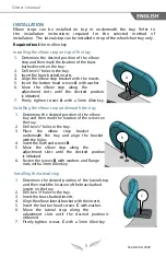
Installing the elbow stop on top of the tray 

1. Determine  the  desired  position  of  the  elbow

stop and then mark the location of the brass

barbed inserts on the tray.

2. Drill two ¼” holes in the tray.

3. Insert the brass barbed inserts.

4. Align the elbow stop bracket with the  inserts.

5. Insert  the  button  head  screws

  A

  with washer.

6. Move  the  elbow  stop  along  the

adjustment  slots  until  the  desired  position 

is obtained.

7. Firmly  tighten  screws 

with  a  3mm  Allen key.

Installing the elbow stop underneath the tray 

1. Determine  the  desired  position  of  the  elbow

tray and then mark the location of the screws on

the tray.

2. Drill two ¼” holes in the tray.

3. Place  the  elbow  stop  bracket

underneath  the  tray  and  align  the  bracket 

with the holes.

4. Insert the flat head screws 

B

.

5. Move  the  elbow  stop  along  the

adjustment  slots  until  the  desired  position 

is obtained.

6. Fasten the screws 

B

 with washers and flange

nuts, with a 3mm Allen key.

Owner’s manual 

A


Installing the lateral stop 

1. Determine  the  desired  position  of  the  lateral stop

and then mark the location of the brass barbed

inserts on the tray.

2. Drill two ¼” holes in the tray.

3. Insert the brass barbed inserts.

4. Align the elbow lateral bracket with the inserts.

5. Insert  the  button  head  screws

  C

  with washer.

6. Move  the  lateral  stop  along  the

adjustment  slots  until  the  desired  position is 

obtained.

7. Firmly  tighten  screws 

with  a  3mm  Allen key.

C


5

September 20

22

Summary of Contents for ELBOW STOPS

Page 1: ...et contains important information about this product Please give to the owner upon delivery INHIBITEURS D AVANT BRAS Manuel d utilisation Ce livret contient d importantes informations relatives ce pro...

Page 2: ...cations made to the product without the prior written consent of Physipro Inc PRODUCT INFORMATION Date of purchase _____________________________________________________ Supplier ______________________...

Page 3: ...ements of California 116 117 NFPA 701 CE marking and NF EN1021 1 EN1021 2 norms COMPOSITION Rigid structure Aluminum bracket Aluminum plate Padding inch soft memory foam Neoprene cover with zipper TEC...

Page 4: ...rs Always use the provided mounting hardware to install your upper limb support Never push or lift wheelchair with an upper limb support doing so may cause the device to detach from the wheelchair whi...

Page 5: ...lbow stop underneath the tray 1 Determine the desired position of the elbow tray and then mark the location of the screws on the tray 2 Drill two holes in the tray 3 Place the elbow stop bracket under...

Page 6: ...h 5 Remove all debris on the padding surface 6 With a mix of water and a soft soap or neutral detergent gently wipe clean the padding 7 Remove excess moisture by lightly patting the surfaces with a cl...

Page 7: ...se refrain from using your product until an inspection has been made by a qualified technician In the event you do not receive satisfactory warranty service please write directly to Physipro Inc at th...

Page 8: ...onsentement crit Pour Physipro Inc votre satisfaction demeurera toujours une priorit INFORMATIONS SUR LE PRODUIT Date d achat _________________________________________________________ Distributeur ___...

Page 9: ...117 NFPA701 et aux normes NF EN1021 1 EN1021 2 et CE COMPOSITION Structure rigide Support en aluminium Plaque en aluminium Rembourrage Mousse m moire molle po Housse en n opr ne avec fermeture clair...

Page 10: ...hnique la mobilit fauteuil propulsion manuelle ou lectrique Utiliser toujours la quincaillerie fournis avec le support pour membre sup rieur pour l installation Ne jamais soulever le fauteuil roulant...

Page 11: ...nt les vis A Installer l inhibiteur lat ral sur le dessous de la table 1 D terminer la position d sir e de l inhibiteur et marquez l emplacement des inserts en laiton sur la table 2 Percez deux trous...

Page 12: ...chiffon humide 7 ponger doucement la surface du coussin en mousse avec un chiffon propre pour absorber le surplus d humidit et laisser s cher compl tement l air libre 8 Lorsque tous les composants so...

Page 13: ...Le produit ne doit pas tre utilis ou modifi avant l inspection du r parateur d sign Dans le cas o vous ne recevez pas un service satisfaisant s il vous pla t crivez directement Physipro Inc l adresse...

Page 14: ...NOTES 14...

Page 15: ...NOTES 15 Septembre 2022...

Page 16: ...nue Sud Sherbrooke Qu bec J1G 2R7 Canada T 1 800 668 2252 F 819 565 3337 info physipro com order physipro com Europe Importateur SASU PHYSIPRO IMPORT T 02 41 69 38 01 F 02 41 69 43 32 contact physipro...

Reviews: