background image

22

XL5 / XL5 CI wheelchair

ENGLISH

7. Front Wheels

7.1  Front Wheels Installation

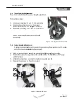
To change the wheels, simply follow these instructions:

1.  Determine the front wheel position on the fork. Refer to Appendix A.

2.  Insert screw 

A

 in the corresponding hole with both spacers 

B

 between the 

wheel and fork on each side.

3.  Put bolt 

C

 at the end of screw 

A

 and tighten with two 13 mm wrenches.

*Note - Once tightened, the wheel must turn easily

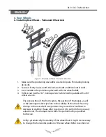
Figure 18 : Front Wheels Installation

A

C

B

B

This step is required when a change to the front wheels’ position or seat 

height has been made.  It will help to always have a straight line, to allow 

easier propulsion.  Please refer to section 5.4

Summary of Contents for Xl 5 ci

Page 1: ...Owners Manual This manual contains important informations about this product Please pass it to the final user upon delivery...

Page 2: ...s and settings Physipro inc strongly recommends you consult a qualified professional Physipro inc provides you with specific verifications you should perform on a regular basis in order to optimize th...

Page 3: ...nt Wheel Axle 18 6 2 Installing Rear Wheels Quick Release Axle 19 6 3 Adjusting Quick Release Axle 19 6 4 Adjusting the Wheelbase forward and back 20 6 5 Rear Wheel Lateral Adjustment 21 7 Front Wheel...

Page 4: ...ng Armrest Back 31 10 3 2 Armrest Height Adjustment 31 11 Footrests 32 11 1 Swing in swing out Footrests 32 11 2 Height Adjustment 32 11 3 Angle and Depth Adjustable Footplates optional 33 11 4 Footpl...

Page 5: ...ositioning Strap 40 15 1 Seat Positioning Strap 40 16 Folding Unfolding the Wheelchair 40 16 1 Folding Wheelchair 40 16 2 Unfolding the Wheelchair 41 16 3 Folding Backrest Optional 42 16 4 Transit use...

Page 6: ...re also available Please contact us for more details or refer to the purchase order Figure 1 Wheelchair Main Components Padded Swing Away Armrest Frame Seat Flip up Footplate Front wheel Anti Tip Tube...

Page 7: ...eat depth available in option F Overall Width Seating Width 8 G Rear Wheel Diameter 20 22 24 or 26 H Front Wheel Diameter 4 5 6 7 or 8 I Transport Weight XL5 Standard 32 2 lb CI Model 27 6 lb Pediatri...

Page 8: ...thly Check for noise vibration or a change in ease of use Make sure that the wheel locks do not interfere with tires when rolling Verify that the wheel locks are easy to engage Make sure the anti tip...

Page 9: ...proach an obstacle whose height could reduce the stability of the wheelchair Never carry passengers Do not fasten objects to the backrest except those provided with the wheelchair Do not attempt to ti...

Page 10: ...n of two assistants is required to go up or down stairs To do so one assistant should stand behind the wheelchair holding the push handles The second assistant should maintain a fixed part of the fram...

Page 11: ...nce 1 Turn the front wheels parallel to the target object you are transferring 2 Make sure the wheel locks are engaged to avoid the chair moving 3 Remove or swing away the armrest 4 Remove or swing aw...

Page 12: ...eight limit please refer to table 1 page 6 Terrain Do not use your wheelchair on sand or gravel surface soils This may damage wheels or axles or loosen fasteners of your chair Seat Positioning Strap A...

Page 13: ...ious disinfect the seat the armrests the backrests and every other surface daily with a disinfectant Do not rinse or wipe just let it dry 3 3 3 Storage Store your chair in a clean dry area If stored f...

Page 14: ...A and B tighten 4 If you reduce the depth you will have to take off the tube extensions otherwise you will have to move them Read the following sections Figure 7 Seat Depth Modification B Once the des...

Page 15: ...ure 10 Seat Height The combination of the front and rear wheels size The position of the rear wheels anchoring mechanism 5 1 Front and Rear Wheels Combination The combination of the front and rear whe...

Page 16: ...l with the quick release push button refer to section 6 1 2 Using two 10 mm wrenches unscrew screws A 3 Adjust anchoring mechanism to the desired position 4 Replace screws A tighten 5 Reinstall the re...

Page 17: ...e installed the wheel should turn easily Figure 12 Changing the front wheels position 5 4 Caster Angle Adjustment To allow easier propulsion the caster housing should always be at a 90 angle to the fl...

Page 18: ...a 3 4 socket wrench The size position of the front casters the position of the brakes as well as the anti tippers directly relate to the stability of the wheelchair Any change to the rear wheel size p...

Page 19: ...t and lint to ensure positive locking and proper operation 6 2 Installing Rear Wheels Quick Release Axle 1 Make sure the positioning device E is inserted in plate F including locking device G 2 Secure...

Page 20: ...the rear wheel refer to section 6 1 or 6 2 2 Unscrew nut A with a 1 1 8 wrench to free washers B and C 3 Slip positioning mechanism D in the slot of the anchoring plate and install washer C at the de...

Page 21: ...ighten nut A and B to release the positioning device C with the use of a 1 1 8 wrench 3 Unscrew or screw nut A and B to move the positioning device in or out 4 Tighten nut A and B with the 1 1 8 wrenc...

Page 22: ...esponding hole with both spacers B between the wheel and fork on each side 3 Put bolt C at the end of screw A and tighten with two 13 mm wrenches Note Once tightened the wheel must turn easily Figure...

Page 23: ...emoved modify the angle to meet your client s needs 3 When the desired angle is reached put the screw A in one of the preset holes 4 Tighten Figure 19 Back Angle Modification Note There is a 5 angle b...

Page 24: ...eels 2 Remove the backrest 3 Unscrew bolt A to remove the back posts 4 Remove the armrest hardware B screw C and screw H on the small tube 5 Remove bolt D 6 Using a flat punch remove sleeves E to rele...

Page 25: ...ottom part of the dynamic back post by re inserting the two sleeves E 8 Re install bolts J and armrest hardware 9 Re install back post and backrest 10 Replace armrest and rear wheels Figure 22 Dynamic...

Page 26: ...for a softer response 4 Make sure to adjust both sides as desired A Figure 25 Dynamic Backrest option Stiffness Adjustment 8 3 Backposts Height Modification The XL5 XL5 CI wheelchair offers 3 differen...

Page 27: ...rubber handle 2 Insert the aluminum spacers A at the end of each handle 3 With a 4 mm Allen key tighten screw B 8 7 2 Folding 1 Press push button C 2 Rotate handle D to keep button C depressed 3 Pres...

Page 28: ...oating using a utility knife 2 Using a 5 mm allen key insert bolt B in the connecting piece A to install it into the back tube receiver 3 Install the pushhandle into the connecting piece and screw bol...

Page 29: ...raighten When straightening the canvas make sure the seat rails are anchored properly 8 9 Angle adjustment of the pushhandles 1 Depress both push buttons A simultaneously This will allow the handles t...

Page 30: ...is reached release latch B making sure the armrest is properly anchored in the right adjustment hole Figure 29 Type U Armrest 10 2 Armrests Type T 10 2 1 Removing armrest 1 Push the release latch A 2...

Page 31: ...in the right hole 4 Tighten Figure 31 Type L Armrest A After any adjustments make sure all attaching hardware is tightened securely otherwise injury or damage may occur Never operate or replace flip b...

Page 32: ...e 2 Rotate the footrest inward until it locks into place on locking bolt 3 To swing out press handle A to unlock the footrest and rotate outward Figure 32 Swing out Footrests 11 2 Height Adjustment 1...

Page 33: ...2 For a depth adjustment slide forward or backward the footrest on its rail 3 Re tighten once the adjustment is done Figure 34 Footplates Adjustment 11 4 Footplate Vertical Adjustment Only available...

Page 34: ...5 Folding Footplate To fold simply pivot footplate upward to vertical position Figure 36 Footrest Folding Do not lift the wheelchair using its footrests to avoid injuries or damages to your wheelchai...

Page 35: ...1 Place the legrest into the receiver on front frame tube with the legrest facing outward from the frame 2 Rotate the legrest inward until it locks into place on locking bolt 3 To remove that leg rest...

Page 36: ...rame tube to the desired height 3 Replace screw A tighten Figure 38 Articulated Legrest Height Adjustment 12 3 Angle adjustment 1 To raise legrest hold the lower part of the footrest while pulling it...

Page 37: ...justment and Applying Brakes 13 1 1 To Apply Brakes 1 Push the handle forward to apply the brakes 2 Pull the handle backward to release the brakes B A When breaks are applied the breaking stop must si...

Page 38: ...osen screw A using a 10mm wrench or ratchet 2 As needed move the brake assembly B forward or backward 3 Tighten screw A Figure 41 Adjustment and Applying Brakes 13 2 2 To apply brakes 1 Pull the handl...

Page 39: ...st tipover Ensure both anti tippers are adjusted to the same mounting hole 14 Anti Tip Tubes 14 1 Inserting Anti tippers In Receiver 1 Press the rear anti tipper release pin A on the anti tipper tube...

Page 40: ...ust slide the strap A into the plastic buckle B in order to lengthen or shorten the belt Figure 43 Seat Positioning Strap 16 Folding Unfolding the Wheelchair 16 1 Folding the Wheelchair 1 Swing legres...

Page 41: ...seat rails fully seated 4 Install Stabilizer Bar Refer to installing the stabilizer bar in section 8 6 if installed 5 Reinstall all postural components Note Ensure that the footrest is locked prior t...

Page 42: ...ovided securement points during transportation Never fix any anchor cable on any other part of the wheelchair Furthermore you have to install the cables as recommended by Transport Canada for maximum...

Page 43: ...ording to the desired seat angle 2 Select the configurations of the front and rear wheels in accordance with the height difference previously obtained by increment of Rear Floor to Seat Height Chart R...

Page 44: ...15 16 16 C 16 16 17 17 D 16 17 17 18 18 Front wheel diameter POSITION 4 5 6 7 8 A 17 18 18 19 19 B 18 18 19 19 20 C 18 19 19 20 20 D 19 19 20 20 21 Front wheel diameter POSITION 4 5 6 7 8 A 13 14 B 1...

Page 45: ...me Short Fork XL5 ci Hemi Frame Short Fork Front wheel diameter POSITION 4 5 6 7 8 A 15 15 B 15 13 13 C 13 13 14 14 D 13 14 14 15 15 Front wheel diameter POSITION 4 5 6 7 8 A 15 15 B 15 11 12 C 11 12...

Page 46: ...wheel positions and frame type The tilt degrees listed in the table above were determined according to a depth of 16 The angle of tip of the XL5 XL5 CI wheelchair must not exceed 15 A greater angle c...

Page 47: ...19 20 19 21 MEDIUM 19 18 20 21 20 22 MEDIUM 22 LONG 20 19 21 LONG 21 20 22 LONG 22 NEED A LONG EXTENSION ROD KIT Configuration restrictions apply when the user weight is over 25 kg and up to 75 kg The...

Page 48: ...nt Wheels and Tires Check tire inflation pressure if applicable P P Ensure the fork turns around its axle P P Check if tires are worn P P Ensure the fork and nuts are secured and stable P P Rear Wheel...

Page 49: ...ch Month Every Six Months Armrests Check if armrests are secured properly and still comfortable P P Footrests Check if footplates are worn P Upholstery Check if seat backrests and armrests are worn P...

Page 50: ...out prior approval If you are dissatisfied with this product send us your comments at the address provided therein and include the name and address of the supplier the delivery date and the serial num...

Page 51: ...elchair of the said person are equipped with restraining systems and tie down devices that are in line with the applicable rules and regulations Physipro inc shall not be held responsible for the misu...

Page 52: ...ue Sherbrooke Quebec J1G 2R7 Canada 1 800 668 2252 info physipro com Europe Village des entrepreneurs 461 rue Saint L onard 49000 Angers France 02 41 69 38 01 contact physipro fr www physipro com Seat...

Reviews: