Programming Manual
PHYTEC Messtechnik GmbH 2008 L-720e_0
67
P
ro
g
ra
m
m
in
g
M
a
n
u
a
l
6.1
Technical Basics
6.1.1
Block Diagram of the pciGrabber-4x4
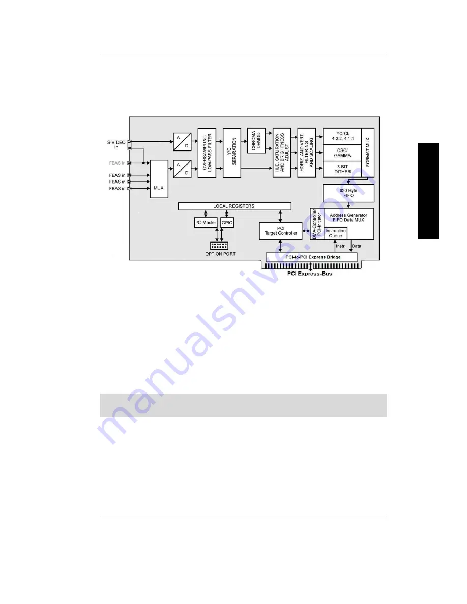
Figure 37: Block diagram VD-012
Figure 37
shows the block diagram of the pciGrabber-4x4. The
composite input signal is connected to a 9:1-video multiplexer, which
is controlled via the PCI-Bus. The following A/D-converter digitizes
this signal. All image sources can be used, which provide a color
video signal corresponding to the CCIR- standard „PAL (B,D,G,H,I)“,
„NTSC (M)“.
In Germany image sources generally provide PAL-signals. In this
manual we assume that always PAL-signal sources are used.


