PCM-072/phyCORE-AM64xx System on Module
L-860e.A0
© PHYTEC America L.L.C. 2022
36
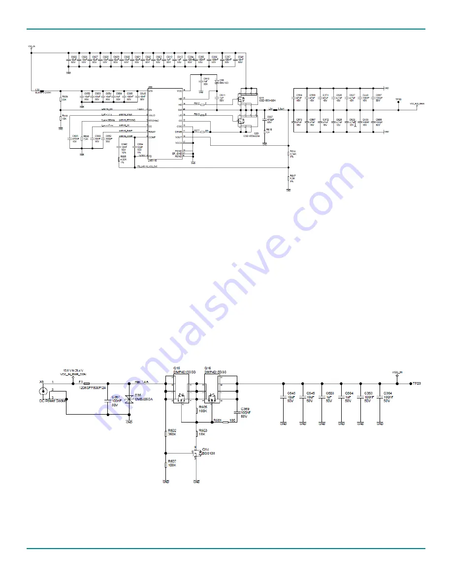
Figure 14. Primary Power VIN(VCC_5V0_MAIN) reference circuit
The primary power reference circuit is simplistic and only provides the functionality of converting an external power input
(VCC_IN) into a 5V power source for the SOM (VCC_5V0_MAIN). The reference circuits below showcase additional
functionality that can be added to the primary power circuit.
is a protection circuit that prevents overloads in
current/voltage from damaging the regulator. It contains:
•
A power socket for connecting an external power source to the system
•
A fuse/diode circuit (F1/D35) that will trip in case of an overload preventing damage to the rest of the circuit
•
A transistor network that provides reverse polarity protection
Figure 15. External power input overload protection reference circuit
is a circuit for measuring the input current to the SOM. It contains:
•
A small resistor (R576) that the current is measured across


