PCM-072/phyCORE-AM64xx System on Module
L-860e.A0
© PHYTEC America L.L.C. 2022
45
6.2.2.3
MMC1 Reference Circuit
An example reference circuit for connecting the MMC1 signals to a micro-SD card reader is shown below.
Figure 19. MMC1 Reference Schematic
6.3 System Boot Configuration
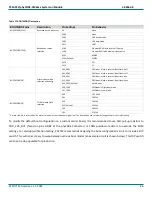
Although most features of the phyCORE-AM64xx SOM are configured or programmed during the initialization routine,
other features which impact program execution must be configured prior to initialization via pin termination. During the
power-on reset cycle, the operational system boot mode of the phyCORE-AM64xx SOM is determined by the configuration
of the BOOTMODE [15:0] signals. The BOOTMODE signals must be held at the desired configuration until X_PORz_OUT
goes high to be properly latched into the system. For development and debugging purposes, the BOOTMODE pins are
available at the phyCORE-Connector and are named X_GPMC0_AD#/BOOTMODE#. These signals are strapped to default
values using on-board resistors.
below lists the various BOOTMODE configurations as well as the default
configuration on the SOM, which is to boot from eMMC with SD card as a backup. Further BOOTMODE options are
discussed in the
AM64xx Technical Reference Manual.


