background image

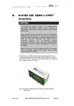
E-650.OE OEM LVPZT Amplifier 


Features 

„


Specially Designed to Drive Multilayer "Bimorph" 
Actuators 


„


8 W Peak Power  

„


Output Voltage Range 0 to 60 V + One Fixed Voltage 


„


+/-15 V Operating Voltage 

Operation : 

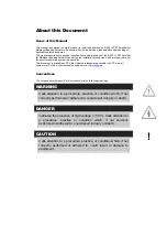
DANGER 


E-650s are amplifiers generating high voltages of up to 
60 V for driving piezo actuators. The output power may 
cause serious injuries. 

Working with these devices or using piezoelectric products 
from other manufacturers we strictly advise you to follow 
the General Accident Prevention Regulations. 

All work done with and on the devices described here 
requires adequate knowledge of handling high voltages. 

CAUTION 

Handle bender actuators (ceramic elements!) with care! Do 
not drop a bender actuator; avoid subjecting it to any kind 
of mechanical shock. 

 
Output voltage is controlled by an analog signal ranging from 0 
to 10 V. Multiplying by the gain factor of 6, an output voltage 
range of 0 to 60 V results. A fixed voltage of 60 V is also 
available for biasing the bender actuator. 

www.pi.ws 

E-650 LVPZT Amplifier PZ 97E Release 1.0.3 

Page 11 

Summary of Contents for E-650

Page 1: ...ators Release 1 0 3 Date 2005 05 12 This document describes the following product s E 650 00 LVPZT Amplifier E 650 OE LVPZT OEM Amplifier Physik Instrumente PI GmbH Co KG Auf der R merstr 1 76228 Karl...

Page 2: ...and normative documents Electromagnetic Emission EN 61000 6 3 EN 55011 Electromagnetic Immunity EN 61000 6 1 Safety Low Voltage Directive EN 61010 1 Electrical equipment which is intended to be integ...

Page 3: ...I GmbH Co KG reserves all rights Use of said texts photographs and drawings is permitted only in parts and only upon citation of the source First printing 2005 05 12 Document Number PZ 97E Release 1 0...

Page 4: ...document is available as PDF file Updated releases are available via FTP or email contact your Physik Instrumente sales engineer or write info pi ws Conventions The notes and symbols used in this manu...

Page 5: ...Rear Panel Elements 6 4 Operation 7 4 1 Operating Requirements 7 4 2 Operating Modes 7 5 E 650 00 Technical Data 8 5 1 Block Diagram 8 5 2 Pin Assignment 8 5 3 E 650 PS Power Supply 9 5 4 Specificati...

Page 6: ...Pose PCBs only on conductive surfaces such as ESD safe transport containers envelopes foam Electronic subassemblies must always be kept and transported shipped in conductive packaging Make sure that n...

Page 7: ...cautions CAUTION Handle bender actuators ceramic elements with care Do not drop a bender actuator avoid subjecting it to any kind of mechanical shock www pi ws E 650 LVPZT Amplifier PZ 97E Release 1 0...

Page 8: ...LCD Voltage Display Output Voltage Range 0 to 60 V One Fixed Voltage for Full Differential Voltage Control The PICMA actuators require full differential voltage control with constant voltages of 0 V a...

Page 9: ...Amplifier for Multilayer Bender Actuators E 650 OE LVPZT OEM Amplifier for Multilayer Bender Actuators E 650 PS Power Supply ID 2580 E 650 90 OEM cable for PZT connection DB9pin open end 1 5 m www pi...

Page 10: ...n potentiometer for DC bias 0 to 60 Volts PZT Monitor control voltage output monitor 0 10 V PZT Output DB 9 pin connector for PZT connection Control Input Analog control voltage input BNC connector Po...

Page 11: ...id subjecting it to any kind of mechanical shock 4 1 Operating Requirements A power supply for 2A 15 VDC is required Recommended is the use of the 650 PS power supply 4 2 Operating Modes External oper...

Page 12: ...n 1 is internally connected to pin 2 and pin 4 is internally connected to pin 5 so that the appropriate output voltages are present on both pins of such a pair in parallel It is also possible to conne...

Page 13: ...t limitation Short circuit proof Control input voltage 0 to 10 V Output voltage 0 to 60 V one additional fixed voltage of 60 V Polarity positive DC offset setting 0 to 60 V w 10 turn pot Voltage gain...

Page 14: ...s only on conductive surfaces such as ESD safe transport containers envelopes foam Electronic subassemblies must always be kept and transported shipped in conductive packaging Make sure that no conduc...

Page 15: ...s we strictly advise you to follow the General Accident Prevention Regulations All work done with and on the devices described here requires adequate knowledge of handling high voltages CAUTION Handle...

Page 16: ...rage output current 5 ms 60 mA per channel Current limitation Short circuit proof Control input voltage 0 to 10 V Output voltage 0 to 60 V one additional fixed voltage of 60 V Polarity positive Voltag...

Page 17: ...E 650 OE OEM LVPZT Amplifier www pi ws E 650 LVPZT Amplifier PZ 97E Release 1 0 3 Page 13 6 3 E 650 OE Pin Assignment Fig 6 E 650 OE Pin Assignment...

Reviews: