background image

Technical Note 

MP165

E

, valid for F-712.PM1 

BRo, 14/11/2017 


Physik Instrumente (PI) GmbH & Co. KG, Auf der Roemerstrasse 1, 76228 Karlsruhe, Germany 

Page 5 / 17 

Phone: +49 721 4846-0, Fax: +49 721 4846-1019, Email 

info@pi.ws

www.pi.ws


To ensure safe operation of the photometer, avoid the following situations: 


Storing outside or in a humid environment or other unfavorable conditions 


Excess load while transporting, e.g., due to improper packaging 


Operating in a dangerous environment (explosive gases, vapors, dust etc.) 


Avoid contamination of the optical input of the photometer. 


Seal the optical input with the protective cap supplied if an optical signal is not 

connected and before cleaning the photometer. 


Organizational Measures 

User Manual 


Always keep this user manual available when using the photometer. 

The latest versions of the user manuals are available on our website (p. 3) for 

download. 


Add all information from the manufacturer such as supplements or technical notes to 

the user manual. 


If you give the photometer to other users, also include this user manual as well as all 

other relevant information provided by the manufacturer. 


Only use the device on the basis of the complete user manual. Missing information due 

to an incomplete user manual can result in damage to equipment. 


Only install and operate the photometer after you have read and understood this user 

manual. 

Personnel Qualification and Instruction 

The photometer may only be installed, started up, operated, maintained, and cleaned by 

authorized and appropriately qualified personnel. Persons who are in charge of using the 

photometer for measuring must be familiar with the accident prevention regulations applicable 

to their area. 
Periodic concentration from the user is required when handling the photometer during the 

measuring task. For this reason, the photometer should not be used in environments that 

themselves require the uninterrupted attention of the user. Instruction of the user must include 

any possible risks. 

Summary of Contents for F-712.PM1

Page 1: ...Co KG Auf der Roemerstrasse 1 76228 Karlsruhe Germany Phone 49 721 4846 0 Fax 49 721 4846 1019 Email info pi ws www pi ws F 712 PM1 Photometer 400 1550 nm Wavelength Range to 1 mA Input Current 20 kH...

Page 2: ...Information and Product Labeling 6 Features and Applications 7 Product View 7 Front Panel 7 Rear Panel 8 Scope of Delivery 8 Unpacking 9 Connecting the power supply to the photometer 9 Startup and Op...

Page 3: ...s that are supplied with software CD in the scope of delivery access to the manuals is protected by a password Protected manuals are only displayed on the website after entering the password The passw...

Page 4: ...ntended for stationary use to measure optical power The photometer does not protect the user against radiation hazards from the objects being measured If the photometer is subject to mandatory calibra...

Page 5: ...ormation from the manufacturer such as supplements or technical notes to the user manual If you give the photometer to other users also include this user manual as well as all other relevant informati...

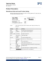
Page 6: ...beling Type plate left and calibration label right on the bottom of the photometer Category Value Meaning Type PM16 Product name of the manufacturer GO item number 15305524 Item number of the manufact...

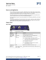
Page 7: ...rrent input is activated The large wavelength range of the photometer enables working in both the visible and infrared range without switching Thanks to the precision logarithmic output signal the pho...

Page 8: ...x connector MC1 5 3 STF Connection for the supply voltage Pin assignment see p 16 Scope of Delivery Order number Quantity Components F 712 PM1 1 Photometer 1 Protective cap for the optical input 1 Ada...

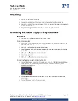
Page 9: ...er cord is not connected to the power socket Tools and accessories Included 24 V wide range input power supply for line voltages between 100 and 240 VAC at 50 or 60 Hz Alternative Sufficiently dimensi...

Page 10: ...f the photometer is moved from a cold to a warm environment start it up only after the temperature of the photometer has adapted itself to the ambient temperature Avoid contamination of the optical in...

Page 11: ...can be calculated from the output voltage of the photometer Use the following U Output voltage U ANALOG OUT V c Intercept V see calibration certificate value for logarithmic output signal page 5 m Sl...

Page 12: ...photometer can lead to significant deviations of the measured values Before cleaning disconnect the photometer from the power supply by pulling the power plug Before cleaning the photometer seal the o...

Page 13: ...Other enquires and orders Contact your PI representative or send us an email mailto service pi de If you have questions concerning your system have the following information ready Product and serial n...

Page 14: ...current 1 mA Average noise 120 pA Output Connectors BNC Output signal Analog logarithmic Voltage range 5 to 5 V typ Bandwidth 3dB 20 kHz Logarithmic increase 1 V 10 dB Output voltage at 85 mW 1550 nm...

Page 15: ...t responsivity distribution of your photometer Figure 4 Typical responsivity curve depending on the wavelength Maximum Ratings Maximum operating voltage Maximum operating frequency unloaded Maximum po...

Page 16: ...19 Email info pi ws www pi ws Dimensions Dimensions in mm Note that the decimal places are separated by a comma in the drawings Figure 5 F 712 PM1 Pin Assignment POWER 12 to 24 V DC Phoenix Connector...

Page 17: ...member states via the municipal residual waste Dispose of your old equipment according to international national and local rules and regulations In order to fulfil the responsibility as the product ma...

Reviews: