background image


5 Installation 

M-687.UN XY Stage 

MP100E 

Version: 1.3.0 

19 

Requirements 


You have read and understood the general notes on installing (p. 15)


The M-687.UN is 

not

 connected to the controller. 

Tools and accessories 


000031657 screw set (p. 10) 

Mounting the M-687.UN onto a surface 

1.


Move the motion platforms of the M-687.UN by hand until all countersunk holes in the 

base body are accessible (refer to illustration above). 

2.


Fix the M-687.UN with the four M5 screws supplied. 

3.


Make sure that the screw heads are fully countersunk. 


5.4


Mounting a Positioner on the M-687.UN 


NOTICE 


Impermissibly high load on the XY stage! 

An impermissibly high load impairs the motion of the platforms and can damage the XY stage. 


For mounting type and mass of the load, pay attention to the maximum permissible forces 

that, according to the specification (p. 37), are allowed to act on the platforms. 


NOTICE 


Excessively long screws! 

The M-687.UN can be damaged by excessively long screws. 


Pay attention to the depth of the mounting holes in the upper platform (p. 40)


Only use screws of the correct length for the respective mounting holes. 


INFORMATION 


An adapter plate (p. 10) is mounted on the upper motion platform of the M-687.UN, which 

must be removed before mounting certain positioners (e.g., P-736.ZCN2S and P-736.ZRN2S). 


Requirements 


You have read and understood the general notes on installing (p. 15)


The M-687.UN and the positioner to be mounted are 

not 

connected to the respective 

controller. 

Summary of Contents for M-687.UN

Page 1: ...49 721 4846 0 Fax 49 721 4846 1019 Email info pi ws www pi ws MP100E M 687 UN XY Stage User Manual Version 1 3 0 Date 17 03 2022 This document describes the following product M 687 UN XY stage for inv...

Page 2: ...I GmbH Co KG Karlsruhe Germany The text photographs and drawings in this manual are protected by copyright With regard thereto Physik Instrumente PI GmbH Co KG retains all the rights The use of any te...

Page 3: ...Controllers 11 3 5 Accessories 11 3 6 Technical Features 12 3 6 1 Linear Encoder 12 3 6 2 Limit Switches 12 3 6 3 Reference Switch 12 4 Unpacking 13 5 Installation 15 5 1 General Notes on Installing...

Page 4: ...37 10 1 Specifications 37 10 1 1 Data Table 37 10 1 2 Limit Switch Specifications 38 10 1 3 Reference Switch Specifications 38 10 1 4 Maximum Ratings 38 10 2 Ambient Conditions and Classifications 39...

Page 5: ...al understanding of basic servo systems as well as motion control concepts and applicable safety procedures The latest versions of the user manuals are available for download p 3 on our website 1 2 Sy...

Page 6: ...with sensor evaluation for closed loop operation of positioners e g C 867 controller Amplifier Electronics without sensor evaluation for open loop operation of positioners Load capacity Maximum load c...

Page 7: ...INFORMATION If a manual is missing or problems occur with downloading Contact our customer service department p 35 Downloading Manuals 1 Open the website www pi ws 2 Search the website for the product...

Page 8: ......

Page 9: ...e or the environment The M 687 UN is only intended for horizontal mounting It is only possible to use the M 687 UN as intended when it is completely mounted and connected The M 687 UN uses PILine ultr...

Page 10: ...connectors out of the electronics during operation If possible use screws to secure the connectors against being pulled out of the electronics If a protective earth conductor is not or not properly c...

Page 11: ...otes If you give the M 687 UN to a third party include this user manual as well as other relevant information provided by the manufacturer Do the work only if the user manual is complete Missing infor...

Page 12: ......

Page 13: ...Features 12 3 1 Product View Figure 1 M 687 UN product view 1 Lower platform X axis 2 Upper platform Y axis 3 Base body 4 000029788 adapter plate 110 mm 160 mm 5 Protective earth connection 6 Connect...

Page 14: ...me Symbol for the protective earth conductor marks the protective earth connector of the M 687 UN p 16 Axis X Connection socket for controller cable X axis Axis Y Connection socket for controller cabl...

Page 15: ...perture P 541 Z Flat nanopositioner Z stage with large aperture P 545 2R8S PInano XY piezo system clear aperture for microscope slides 200 m 200 m piezoresistive sensors with USB digital controller P...

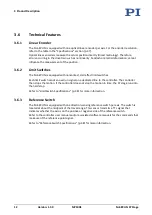
Page 16: ...ches Each limit switch sends an overrun signal on a dedicated line to the controller The controller then stops the motion If the controller does not stop the motion in time the XY stage runs into the...

Page 17: ...UN is always horizontal If the M 687 UN must be brought to a vertical position during installation secure the platforms against slipping 1 Unpack the M 687 UN with care 2 Compare the contents with the...

Page 18: ......

Page 19: ...uching the contacts in the connection sockets of the M 687 UN or in the connectors of the connected cables could lead to minor injuries from electric shock In addition the piezo actuators could be des...

Page 20: ...When moving the platform in a power off state manually differences in the holding force may be noticeable across the travel range There are mechanical reasons for fluctuations in the holding force and...

Page 21: ...onnected to the controller Tools and accessories Suitable protective earth conductor Cross sectional area of the cable 0 75 mm2 M4 screw set supplied for connecting the protective earth conductor p 10...

Page 22: ...ed base body will increase wear and reduce accuracy Mount the M 687 UN onto a flat surface The recommended flatness of the surface is 5 m For applications with large temperature fluctuations Only fix...

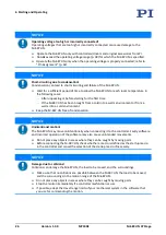
Page 23: ...igh load impairs the motion of the platforms and can damage the XY stage For mounting type and mass of the load pay attention to the maximum permissible forces that according to the specification p 37...

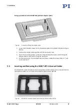
Page 24: ...le tool for tightening the screws Fixing a positioner to the M 687 UN with adapter plate Figure 4 M 687 UN Threaded holes in the upper platform hatched arrows 8 M4 black arrows 4 M3 gray arrows 4 M6 1...

Page 25: ...he mounting position so that the threaded holes that were used for fixing the adapter plate can be used for fixing the positioner 4 Fix the positioner to the threaded holes with three suitable M4 scre...

Page 26: ...that it makes contact on two sides 3 Slowly slide the universal holder towards the clip spring until it reaches the edge and the clip spring is compressed 4 On the opposite side press the universal h...

Page 27: ...irst cable to the Axis X socket of the M 687 UN 2 Connect the D sub connector m on the other end of the cable to the Axis 1 socket of the controller 3 Connect the MDR connector of the second cable to...

Page 28: ......

Page 29: ...e g in the case of modifications reconnect the M 687 UN to the protective earth conductor before restarting NOTICE Destruction of the piezo motor due to electric flashovers Using the M 687 UN in envi...

Page 30: ...ronment or from a warm into a cold environment Keep the M 687 UN free of condensation NOTICE Unintentional motion The M 687 UN may move unintentionally when connecting it to the controller Faulty soft...

Page 31: ...o the velocity acceleration deceleration and load in small steps only Do not deactivate the limit switches in the software Test the function of the limit switches at low velocities only Stop motion im...

Page 32: ...rm I term D term acceleration velocity refer to the controller manual Save the new parameter values to a positioner database on the PC or to the nonvolatile memory of the controller for future use ref...

Page 33: ...All connections on the controller have been made refer to the controller manual Starting and operating the M 687 UN with the C 867 controller Operate one axis of the M 687 UN refer to controller manu...

Page 34: ......

Page 35: ...to distribute the existing lubricant on the guides of the M 687 UN To evenly distribute the existing lubricant on the stage guides do a maintenance run across the entire travel range after 500 hours o...

Page 36: ...E M 687 UN XY Stage 7 3 Cleaning the M 687 UN Requirements You have disconnected the M 687 UN from the controller Cleaning the M 687 UN If necessary clean the M 687 UN surface using a cloth dampened w...

Page 37: ...eased wear Warped base body Mount the M 687 UN onto a flat surface The recommended flatness of the surface is 5 m For applications with large temperature fluctuations Only mount the M 687 UN on surfac...

Page 38: ......

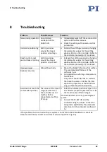
Page 39: ...on Product and serial numbers of all products in the system Firmware version of the controller if applicable Version of the driver or the software if applicable Operating system on the PC if applicabl...

Page 40: ......

Page 41: ...Assignment 42 10 1 Specifications 10 1 1 Data Table M 687 UN Unit Tolerance XY Stage for Inverted Nikon Microscopes Active axes X Y Motion and positioning Travel range 135 mm 85 mm Integrated sensor...

Page 42: ...mit switch is passed the signal level changes Normal motor operation low 0 V Limit switch reached high 5 V 10 1 3 Reference Switch Specifications Type Optical sensor Supply voltage 5 V GND supply via...

Page 43: ...a Relative humidity Highest relative humidity 80 for temperatures up to 31 C Decreasing linearly to 50 relative humidity at 40 C Operating temperature 20 C to 40 C Storage temperature 20 C to 75 C Tra...

Page 44: ...ata 40 Version 1 3 0 MP100E M 687 UN XY Stage 10 4 Dimensions Figure 9 M 687 UN XY stage with installed 000029788 adapter plate Dimensions in mm Note that a comma is used in the drawings instead of a...

Page 45: ...10 Technical Data M 687 UN XY Stage MP100E Version 1 3 0 41 Figure 10 000029788 adapter plate for M 687 UN Dimensions in mm Note that a comma is used in the drawings instead of a decimal point...

Page 46: ...Output Negative end limit switch active high A4 REFSWITCH Output Reference switch TTL positive A5 NC Not connected A6 VDD Input 5 V A7 USM_P1 Input Piezo voltage ground B1 USM_P2 Input Piezo 71 VAC R...

Page 47: ...ional national and local rules and regulations In order to fulfill its responsibility as the product manufacturer Physik Instrumente PI GmbH Co KG undertakes environmentally correct disposal of all ol...

Page 48: ......

Page 49: ...f conformity were issued according to the following European statutory requirements Low Voltage Directive EMC Directive RoHS Directive The standards applied for certifying conformity are listed below...

Reviews: