background image


10 Technical Data 

46 

Version: 1.2.0 

MP125E 

N­470 Linear Actuator 

10.6


Pin Assignment 

A LEMO connector is used for connecting to the drive electronics: 


Models that are not suitable for use in a vacuum: The connector is located directly on 

the cable of the N-470. 


Vacuum-compatible models: The connector is on the air-side cable (p. 13). The ends of 

the cable on the vacuum and air side of the N-470 have stranded wires for connecting 

to a vacuum feedthrough (p. 22). 


Figure 19:   LEMO connector, 3-pin 


Pin 

Function 

Wire colors for vacuum­compatible models 
Cable on the vacuum 

side 

Cable on the air side 

Input: Piezo + (0 to 80 V) 

Red 

White 

Input: Piezo - (GND) 

Black 

Brown 

Not connected 

--- 

--- 

Cable shield 

Connected to the connector 

shell 

Bare 

Bare 


Summary of Contents for N-470.110

Page 1: ...2019 This document describes the following products N 470 x10 x10Y N 470 x1V x1VY N 470 x1U x1UY PiezoMike linear actuator M10 1 thread N 470 x20 x20Y N 470 x2V x2VY N 470 x2U x2UY PiezoMike linear ac...

Page 2: ...bH Co KG Karlsruhe Germany The text photographs and drawings in this manual are protected by copyright With regard thereto Physik Instrumente PI GmbH Co KG retains all the rights Use of said text phot...

Page 3: ...ct Description 7 3 1 Model Overview 7 3 2 Product View 10 3 3 Product Labeling 12 3 4 Scope of Delivery 13 3 5 Suitable Electronics 14 3 6 Accessories 14 4 Unpacking 15 5 Installation 17 5 1 General N...

Page 4: ...1 3 Ambient Conditions and Classifications 38 10 2 Step Size and Axial Force 39 10 3 Lifetime 40 10 4 Operating Time and Duty Cycle 40 10 5 Dimensions 44 10 5 1 Models with Turned Cable Exit 44 10 5...

Page 5: ...of motion control concepts and applicable safety measures is assumed The latest versions of the user manuals are available for download p 2 on our website 1 2 Symbols and Typographic Conventions The f...

Page 6: ...illustrations may also differ and must not be seen as guaranteed properties 1 4 Other Applicable Documents The devices and software tools from PI mentioned in this documentation are described in their...

Page 7: ...ord shown in the browser window Downloading manuals If you have requested access data for protected contents via a registration page see above Click the links in the browser window to change to the co...

Page 8: ......

Page 9: ...any heat It holds the position with maximum force The N 470 is not intended for continuous operation For further information on the operating conditions of the N 470 see Technical Data p 35 It is onl...

Page 10: ...o an incomplete user manual can result in minor injury and damage to equipment Install and operate the N 470 only after you have read and understood this user manual Personnel qualification The N 470...

Page 11: ...m Position of the cable exit In the product number these are coded as follows by the character following the period Character following the period Meaning Possible values First character Travel range...

Page 12: ...e linear actuator 13 mm M10 1 thread vacuum compatible to 10 6 hPa N 470 21VY PiezoMike linear actuator 13 mm M10 1 thread vacuum compatible to 10 6 hPa turned cable exit N 470 41V PiezoMike linear ac...

Page 13: ...tor 13 mm 9 5 mm 0 375 clamping shank vacuum compatible to 10 6 hPa N 470 22VY PiezoMike linear actuator 13 mm 9 5 mm 0 375 clamping shank vacuum compatible to 10 6 hPa turned cable exit N 470 42V Pie...

Page 14: ...th turned cable exit Figure 1 Models with thread and standard cable exit left N 470 x10 right N 470 x1V 1 Screw head 2 Fine threaded screw rotating 3 Base body 4 M10 1 mounting nut 5 M10 1 mounting th...

Page 15: ...x2V 1 Screw head 2 Fine threaded screw rotating 3 Base body 4 Clamping shank 9 5 mm diameter 6 mm clamping width 5 M9 1 mounting nut 6 Ball tip for connecting to the moving part of the mechanical mou...

Page 16: ...n 12 Version 1 2 0 MP125E N 470 Linear Actuator 3 3 Product Labeling Figure 4 N 470 Product labeling Figure 5 Type plate N 470 410 as an example Figure 6 Laser marking for vacuum compatible models N 4...

Page 17: ...refer to the model C 123456789 Serial number example individual for each N 470 Meaning of the places counting from left 1 internal information 2 and 3 year of manufacture 4 to 9 consecutive numbers O...

Page 18: ...r customer service department p 33 3 6 Accessories Product number Description N 400 A02 Extension cable LEMO connector 3 pin to LEMO connector 3 pin 2 m N 400 A05 Extension cable LEMO connector 3 pin...

Page 19: ...actuator is cleaned once again by wiping and is then shrink wrapped twice in vacuum compatible film Touch the linear actuator only with powder free gloves 1 Unpack the N 470 with care 2 Compare the co...

Page 20: ......

Page 21: ...ligned vertically to the contact surface of the movable part of the mechanical mounting NOTICE Increased wear due to friction Increased friction on the contact surface between the ball tip and the mov...

Page 22: ...470 NOTICE Damage from opening the base body Opening the base body destroys the N 470 Do not open the N 470 NOTICE Damage from unscrewing Completely unscrewing the fine threaded screw from the base b...

Page 23: ...anical mounting The mechanical mounting must be connected to the protective earth conductor INFORMATION Pay attention to the applicable standards for connecting the protective earth conductor Figure 7...

Page 24: ...the N 470 must be electrically conductive The contact resistance at all connection points relevant for attaching the protective earth conductor is 0 1 at 25 A The contact surface of the mechanical mou...

Page 25: ...mounting 7 Optional Turn the screw head of the linear actuator s fine threaded screw into the desired position by hand to avoid longer travel to this position Installing an N 470 with clamping shank 1...

Page 26: ...g the stranded wires and the cable shield Letter Wire color Function Signal Vacuum side actuator cable Air side connecting cable a Red White Piezo voltage 0 to 80 V PIEZO b Black Brown Piezo voltage g...

Page 27: ...wire ends of the N 470 s cables on the vacuum side and on the air side Make sure that the stranded wires are assigned to each other as shown in the connection diagram Connect the cable shield accordin...

Page 28: ......

Page 29: ...eration Establish contact between the N 470 and the protective earth conductor via a sufficiently conductive mechanical mounting p 19 Make sure that the contact resistance is 0 1 at 25 A at all connec...

Page 30: ...ruction of the piezo actuator by electric flashovers Electric flashovers can be caused by moisture high humidity liquids and conductive materials e g metal dust In addition electric flashovers can als...

Page 31: ...rew from the base body leads to damage to the N 470 Do not unscrew the fine threaded screw from the base body of the N 470 NOTICE Fine threaded screw gets stuck The N 470 s fine threaded screw can get...

Page 32: ...dated regularly Install the PI Update Finder from the product CD for the electronics onto your PC and update the positioner database on your PC Further information can be found in the user manual for...

Page 33: ...Actuator MP125E Version 1 2 0 29 When the N 470 is operated in a clean environment no maintenance work is necessary If you would like your device to be serviced please contact our customer service dep...

Page 34: ......

Page 35: ...No or limited motion The cable is not connected correctly or is defective Check the connecting cable Excessive counterforces in the direction of motion Reduce the load Pay attention to the informatio...

Page 36: ......

Page 37: ...tion Product and serial numbers of all products in the system Firmware version of the controller if applicable Version of the driver or the software if applicable Operating system on the PC if applica...

Page 38: ......

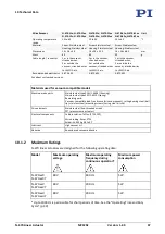
Page 39: ...0 1xx 7 5 N 470 2xx 13 N 470 4xx 26 mm Max step size in step mode 50 nm Typ step size 20 nm Step frequency 2000 Hz Max velocity in full step mode 3 6 mm min Typ velocity in full step mode 2 4 mm min M...

Page 40: ...g N 470 11x N 470 11xx N 470 12x N 470 12xx N 470 21x N 470 21xx N 470 22x N 470 22xx N 470 41x N 470 41xx N 470 42x N 470 42xx Unit Active axis X X X Travel range 7 5 13 26 mm Max step size in step m...

Page 41: ...E 872 401 Ask about customized versions Materials used for vacuum compatible models Machine made parts Stainless steel type 316L 1 4404 housing Stainless steel type 301 1 4310 spring Remaining parts...

Page 42: ...xVY 1100 hPa to 10 6 hPa high vacuum Models N 470 xxU xxUY 1100 hPa to 10 9 hPa ultrahigh vacuum Relative humidity Highest relative humidity 80 for temperatures up to 31 C Decreasing linearly to 50 re...

Page 43: ...l Force The following graph shows the step size of the N 470 against various axial forces The influence of different axial forces on the step size is relatively minor The active feed force is specifie...

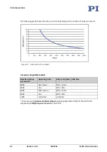
Page 44: ...step size decreases by maximum 30 Figure 12 Typical step size in nm vs number of steps 10 4 Operating Time and Duty Cycle The operating time and duty cycle influence the lifetime of the linear actuat...

Page 45: ...2000 60 s max 20 4 min 2000 10 s 20 40 s 1000 120 s max 40 180 s 1000 10 s 40 15 s 400 unlimited unlimited To be set via the Maximum Motor Output operating parameter 0x9 for the E 872 401 respectively...

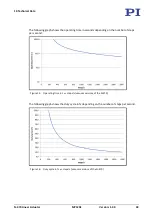
Page 46: ...14 Duty cycle in vs steps s Vacuum compatible models Number of steps per second Operating time Duty cycle max idle time 2000 60 s max 10 9 min 2000 10 s 10 90 s 1000 120 s max 20 8 min 1000 10 s 20 40...

Page 47: ...operating time in seconds depending on the number of steps per second Figure 15 Operating time in s vs steps s vacuum versions of the N 470 The following graph shows the duty cycle in depending on th...

Page 48: ...bsequent sections show the N 470 xxx models with standard cable exit but also apply to the N 470 xxxY models with turned cable exit Take note In the case of the N 470 xxxY models the cable exit is loc...

Page 49: ...70 Linear Actuator MP125E Version 1 2 0 45 10 5 3 Models with Clamping Shank Figure 18 Dimensions N 470 x2x N 470 12x N 470 12xY N 470 22x N 470 22xY N 470 42x N 470 42xY Unit A 48 53 5 68 5 mm B trav...

Page 50: ...cuum compatible models The connector is on the air side cable p 13 The ends of the cable on the vacuum and air side of the N 470 have stranded wires for connecting to a vacuum feedthrough p 22 Figure...

Page 51: ...ational national and local rules and regulations In order to fulfil its responsibility as the product manufacturer Physik Instrumente PI GmbH Co KG undertakes environmentally correct disposal of all o...

Page 52: ......

Page 53: ...tion of Conformity has been issued in accordance with the following European directives Low Voltage Directive EMC Directive RoHS Directive The applied standards certifying the conformity are listed be...

Reviews: