background image


2 Safety 

N­472 Linear Actuator 

MP144E 

Version: 1.3.0 

In this Chapter 

Intended Use .................................................................................................................................. 5 

General Safety Instructions............................................................................................................ 5 


2.1


Intended Use 

The N-472 is a laboratory device as defined by DIN EN 61010-1. It is intended for indoor use and 

use in an environment that is free of dirt, oil and lubricants. 
The N-472 is a linear actuator for integration into mechanical and optomechanical components. 

For integration, the mechanics, in which the N-472 is to be installed, must have suitable 

mountings. 
A piezoelectric motor is installed in the N-472 linear actuator that acts on the fine-threaded 

screw and moves it.  
When at rest, the drive is self-locking and therefore requires no current and generates no heat. 

It holds the position with maximum force. 
The N-472 is not intended for continuous operation. For further information on the operating 

conditions of the N-472, see "Technical Data" (p. 37). 
The intended use of the N-472 is only possible in conjunction with a suitable controller (p. 12), 

which is available from PI. The controller is not included in the scope of delivery of the N-472. 
The controller must provide the required operating voltages. It must also be able to read out 

and process the signals from the position sensors so that the servo control system can function 

properly. 


2.2


General Safety Instructions 

The N-472 is built according to state-of-the-art technology and recognized safety standards. 

Improper use can result in personal injury and/or damage to the N-472. 


Use the N-472 for its intended purpose only, and only when it is in perfect technical 

condition. 


Read the user manual. 


Eliminate any malfunctions that may affect safety immediately. 

The operator is responsible for the correct installation and operation of the N-472. 


2


Safety 

Summary of Contents for N--472 10 Series

Page 1: ...ser Manual Version 1 3 0 Date 29 10 2019 This document describes the following products N 472 x10 x10Y N 472 x1V x1VY PiezoMike linear actuator M10 1 thread N 472 x20 x20Y N 472 x2V x2VY PiezoMike lin...

Page 2: ...GmbH Co KG Karlsruhe Germany The text photographs and drawings in this manual are protected by copyright With regard thereto Physik Instrumente PI GmbH Co KG retains all the rights Use of said text ph...

Page 3: ...7 3 2 Product View 9 3 3 Product Labeling 11 3 4 Scope of Delivery 12 3 5 Suitable Controllers 12 3 6 Technical Features 13 3 6 1 ID Chip 13 4 Unpacking 15 5 Installation 17 5 1 General Notes on Insta...

Page 4: ...0 1 3 Maximum Ratings 40 10 1 4 Ambient Conditions and Classifications 40 10 2 Step Size and Axial Force 41 10 3 Lifetime 42 10 4 Operating Time and Duty Cycle 42 10 5 Dimensions 45 10 5 1 Models with...

Page 5: ...ng of basic servo systems as well as motion control concepts and applicable safety procedures The latest versions of the user manuals are available for download p 3 on our website 1 2 Symbols and Typo...

Page 6: ...ign on the product which refers to detailed information in this manual 1 3 Figures For better understandability the colors proportions and degree of detail in illustrations can deviate from the actual...

Page 7: ...ment p 35 Downloading manuals 1 Open the website www pi ws 2 Search the website for the product number e g N 472 or the product family e g PiezoMike 3 Click the corresponding product to open the produ...

Page 8: ......

Page 9: ...ontinuous operation For further information on the operating conditions of the N 472 see Technical Data p 37 The intended use of the N 472 is only possible in conjunction with a suitable controller p...

Page 10: ...an incomplete user manual can result in minor injury and damage to equipment Install and operate the N 472 only after you have read and understood this user manual Personnel qualification The N 472 ma...

Page 11: ...vacuum Position of the cable exit In the product number these are coded as follows by the character following the period Character following the period Meaning Possible values First character Travel r...

Page 12: ...ator 13 mm M10 1 thread vacuum compatible to 10 6 hPa turned cable exit PiezoMike linear actuators with clamping shank Model Description N 472 120 Closed loop PiezoMike linear actuator 7 mm 9 5 mm 0 3...

Page 13: ...els with thread and standard cable exit example illustration Standard version left and vacuum version right 1 Screw head 2 Fine threaded screw rotating 3 Base body 4 M10x1 mounting nut 5 M10x1 mountin...

Page 14: ...on right 1 Screw head 2 Fine threaded screw rotating 3 Base body 4 Clamping shank 9 5 mm diameter 6 mm clamping width 5 M9x1 mounting nut 6 Ball tip for connecting to the movable part of the mechanica...

Page 15: ...on N 472 Linear Actuator MP144E Version 1 3 0 11 3 3 Product Labeling Figure 4 N 472 Product labeling Figure 5 Type plate N 472 110 as example Figure 6 Laser marking for vacuum compatible models N 470...

Page 16: ...for each N 472 Meaning of each position from the left 1 internal information 2 and 3 year of manufacture 4 to 9 consecutive number Only with models that are not suitable for use in a vacuum C R 00 00...

Page 17: ...b connector m of the linear actuator in which the data on the linear actuator is stored e g linear actuator type serial number date of manufacture hardware version When switched on or rebooted control...

Page 18: ......

Page 19: ...actuator is cleaned once again by wiping and is then shrink wrapped twice in vacuum compatible film Touch the linear actuator only with powder free gloves 1 Unpack the N 472 with care 2 Compare the co...

Page 20: ......

Page 21: ...aligned vertically to the contact surface of the movable part of the mechanical mounting NOTICE Increased wear due to friction Increased friction on the contact surface between the ball tip and the m...

Page 22: ...72 NOTICE Damage from opening the base body Opening the base body destroys the N 472 Do not open the N 472 NOTICE Damage from unscrewing Completely unscrewing the fine threaded screw from the base bod...

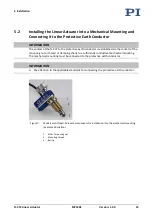
Page 23: ...hed via the contact of the mounting nut or thread or clamping shank to a sufficiently conductive mechanical mounting The mechanical mounting must be connected to the protective earth conductor INFORMA...

Page 24: ...amping width 2 M9 1 mounting nut 3 Ball tip Figure 9 Two linear actuators on a mirror mount example illustration 1 Linear actuators with mounting thread 2 Mechanical mounting for linear actuators fixe...

Page 25: ...ook wrench included in the scope of delivery p 12 When lubricant is to be applied to the contact surface of the movable part of the mechanical mounting Models that are not suitable for use in a vacuum...

Page 26: ...mounting 6 Clamp the N 472 firmly in the mounting Hold the base body and hand tighten the mounting nut of the N 472 with the hook wrench 7 Check that the linear actuator is affixed firmly in the moun...

Page 27: ...s and accessories Suitable vacuum feedthrough Connection on the air side and on the vacuum side connector male or female for the vacuum feedthrough N472B0001 motor sensor cable p 12 Suitable tools for...

Page 28: ......

Page 29: ...ctive earth conductor during operation Establish contact between the N 472 and the protective earth conductor via a sufficiently conductive mechanical mounting p 19 Make sure that the contact resistan...

Page 30: ...ers can be caused by moisture high humidity liquids and conductive materials e g metal dust In addition electric flashovers can also occur in certain air pressure ranges due to the increased conductiv...

Page 31: ...etely unscrewing the fine threaded screw from the base body leads to damage to the N 472 Do not unscrew the fine threaded screw from the base body of the N 472 NOTICE Fine threaded screw gets stuck Th...

Page 32: ...472 Servo mode switched off Motion is commanded with the OMA command The target position is approached in stepping mode When the target position is reached stepping mode is switched off and the N 472...

Page 33: ...r s fine threaded screw into the desired reference position manually Determining the reference position manually 1 Open PIMikroMove and establish communication with the controller in the Start up cont...

Page 34: ......

Page 35: ...Actuator MP144E Version 1 3 0 31 When the N 472 is operated in a clean environment no maintenance work is necessary If you would like your device to be serviced please contact our customer service dep...

Page 36: ......

Page 37: ...y set Load the parameter set from the positioner database that corresponds to the N 472 model If necessary In the PIMikroMove PC program set the parameters of the controller so that they correspond to...

Page 38: ......

Page 39: ...tion Product and serial numbers of all products in the system Firmware version of the controller if applicable Version of the driver or the software if applicable Operating system on the PC if applica...

Page 40: ......

Page 41: ...472 21V N 472 21VY N 472 22V N 472 22VY Unit Active axis X X X X Travel range 7 7 13 13 mm Integrated sensor Incremental optical Incremental optical Incremental optical Incremental optical Sensor sig...

Page 42: ...00 100 N Feed force 22 22 22 22 N Drive properties N 472 110 N 472 110Y N 472 120 N 472 120Y N 472 11V N 472 11VY N 472 12V N 472 12VY N 472 210 N 472 210Y N 472 220 N 472 220Y N 472 21V N 472 21VY N...

Page 43: ...preload measured at 100 m stroke compensated for temperature drift 20 N preload measured over the entire stroke compensated for temperature drift Not suitable for continuous operation Ask about custo...

Page 44: ...Conditions and Classifications The following ambient conditions and classifications for the N 472 must be observed Area of application For indoor use only Maximum altitude 2000 m Air pressure Models N...

Page 45: ...ial Force The following graph shows the step size of the N 472 against various axial forces The influence of different axial forces on the step size is relatively minor The active feed force is specif...

Page 46: ...ime and duty cycle influence the lifetime of the linear actuator In order to prevent overheating and strong wear the operating time and the duty cycle must not exceed the values given in the following...

Page 47: ...The following graph shows the operating time in seconds depending on the number of steps per second Figure 13 Operating time in s vs steps s The following graph shows the duty cycle in depending on th...

Page 48: ...ax idle time 2000 60 s max 10 9 min 2000 10 s 10 90 s 1000 120 s max 20 8 min 1000 10 s 20 40 s 200 unlimited unlimited Set via the Maximum Motor Output operating parameter The following graph shows t...

Page 49: ...nsions in mm Note that a comma is used in the drawings instead of a decimal point 10 5 1 Models with Turned Cable Exit INFORMATION The dimensional drawings in the subsequent sections show the N 472 xx...

Page 50: ...10 Technical Data 46 Version 1 3 0 MP144E N 472 Linear Actuator 10 5 2 Models with M10x1 Thread Figure 17 N 472 11x dimensions travel range...

Page 51: ...10 Technical Data N 472 Linear Actuator MP144E Version 1 3 0 47 Figure 18 N 472 21x dimensions travel range...

Page 52: ...10 Technical Data 48 Version 1 3 0 MP144E N 472 Linear Actuator 10 5 3 Models with Clamping Shank Figure 19 N 472 12x dimensions travel range...

Page 53: ...10 Technical Data N 472 Linear Actuator MP144E Version 1 3 0 49 Figure 20 N 472 22x dimensions travel range...

Page 54: ...nal Input 4 5 V Supply voltage 5 V Input 5 NC Not connected 6 ID_CHIP ID chip data Bidirectional 7 ENCA Encoder channel A differential Output 8 ENCB Encoder channel B differential Output 9 PIEZO Motor...

Page 55: ...ational national and local rules and regulations In order to fulfil its responsibility as the product manufacturer Physik Instrumente PI GmbH Co KG undertakes environmentally correct disposal of all o...

Page 56: ......

Page 57: ...tion of Conformity has been issued in accordance with the following European directives Low Voltage Directive EMC Directive RoHS Directive The applied standards certifying the conformity are listed be...

Reviews: