background image


10 Technical Data 

P-545 Nanopositioners 

PZ272E 

Version: 1.1.0 

43 

10.2.2


P-545.SH4 Microscope Slide and Petri Dish Holder 


Figure 14:   P-545.SH4: Microscope slide and Petri dish holder for P-545 PInano® piezo system with 

U-780.DNS (Nikon version) 


Summary of Contents for P-545

Page 1: ...ear aperture for microscope slides 200 m 200 m 200 m capacitive sensors with USB digital controller P 545 2R8S PInano XY Piezo System PInano XY piezo system clear aperture for microscope slides 200 m...

Page 2: ...I GmbH Co KG Karlsruhe Germany The text photographs and drawings in this manual are protected by copyright With regard thereto Physik Instrumente PI GmbH Co KG retains all the rights The use of any te...

Page 3: ...livery 12 3 5 Accessories 12 3 6 Technical Features 13 3 6 1 PICMA Piezo Actuators 13 3 6 2 Flexure Guides 13 3 6 3 Position Sensors 13 3 7 Integration of the P 545 into Microscopes 14 4 Unpacking 15...

Page 4: ...ons 37 10 1 1 Data Table 37 10 1 2 Maximum Ratings 40 10 1 3 Ambient Conditions and Classifications 41 10 2 Dimensions 42 10 2 1 P 545 Positioner 42 10 2 2 P 545 SH4 Microscope Slide and Petri Dish Ho...

Page 5: ...r in this manual The controller in the system is described in a separate manual p 2 Basic knowledge of control technology drive technologies and suitable safety measures is assumed The latest versions...

Page 6: ...es For better understandability the colors proportions and degree of detail in illustrations can deviate from the actual circumstances Photographic illustrations may also differ and must not be seen a...

Page 7: ...n the website www pi ws 2 Search the website for the product number e g P 545 or the product family e g PInano 3 Click the corresponding product to open the product detail page 4 Click the Downloads t...

Page 8: ......

Page 9: ...n moving is done as follows System Motion Axis 2C8S 2R8S In two axes horizontally X Y 3C8S 3R8S 3D8S In two axes horizontally and in one axis vertically X Y Z The P 545 positioner can only be used as...

Page 10: ...ler If a protective earth conductor is not or not properly connected dangerous touch voltages can occur on the P 545 in the case of malfunction or failure of the system If there are touch voltages tou...

Page 11: ...cal notes If you give the P 545 to a third party include this user manual as well as other relevant information provided by the manufacturer Do the work only if the user manual is complete Missing inf...

Page 12: ......

Page 13: ...s with USB digital controller P 545 2R8S PInano XY piezo system clear aperture for microscope slides 200 m 200 m piezoresistive sensors with USB digital controller P 545 3R8S PInano XYZ piezo system c...

Page 14: ...example and can differ from your positioner model Figure 1 Example view of P 545 1 Platform 2 Cable exit 3 M4 hole for connecting the protective earth conductor 4 Base body X Y Z Positive direction o...

Page 15: ...r each P 545 Meaning of each position from the left 1 internal information 2 and 3 year of manufacture 4 to 9 consecutive number B Made in USA Country of origin B Warning sign Pay attention to the man...

Page 16: ...copes IX2 IX3 M 545 2MN XY stage 25 mm 25 mm micrometer screw high stability compatible with PI piezo stages for Nikon microscopes TI series M 545 2ML XY stage 25 mm 25 mm micrometer screw high stabil...

Page 17: ...ere are no rotating parts or friction The piezo actuators are therefore free of backlash maintenance and wear 3 6 2 Flexure Guides P 545 positioners have flexure guides for friction free motion and hi...

Page 18: ...gauge sensors derive the position information from their expansion Full bridge circuits with several strain gauge sensors per axis improve thermal stability 3 7 Integration of the P 545 into Microscop...

Page 19: ...as well as loss of accuracy Do not touch any sensitive parts e g platform when handling the P 545 1 Unpack the P 545 with care 2 Compare the contents with the scope of delivery according to the contr...

Page 20: ......

Page 21: ...rs can be destroyed by an abrupt contraction Do not open the P 545 Discharge the positioner s piezo actuators before installing Connect the positioner to the switched off PI electronics equipped with...

Page 22: ...e due to incorrectly tightened screws Incorrectly tightened screws can cause damage Pay attention to the torque range p 46 specified for the screws used during installation INFORMATION Extension cable...

Page 23: ...tronics Tools and accessories Suitable protective earth conductor Cable cross section 0 75 mm2 M4 protective earth screw set p 12 supplied for connecting the protective earth conductor Suitable screwd...

Page 24: ...Fix the P 545 onto a flat surface The recommended flatness of the surface is 100 m For applications with large temperature fluctuations Only fix the P 545 onto surfaces that have the same or similar t...

Page 25: ...ing to regulations and without bending them Tools and accessories Mounting kit included in the scope of delivery p 12 Four M4x16 screws Hex key Alternative not included in the scope of delivery Four M...

Page 26: ...oles in the platform example view from above Black arrows Holes for mounting a P 545 3C8S 3R8S or 3D8S Hatched arrows Holes for mounting a P 545 2C8S or 2R8S Requirements You have read and understood...

Page 27: ...of the load as well as heavy loads can overload the platform of the P 545 Mechanical overload can cause damage to the piezo actuators sensors and flexures of the P 545 and lead to loss of accuracy Av...

Page 28: ...ould be damaged by screws inserted too deeply Pay attention to the depth of the mounting holes in the platform p 42 Use screws of the correct length for the respective mounting holes only INFORMATION...

Page 29: ...ter of load at an unsuitable position Figure 11 Tall load and center of load too far above the platform Figure 12 Unwanted lever effect and center of load on the side of the platform Requirements You...

Page 30: ...ts You have read and understood the general notes on installation p 17 The P 545 is not connected to the electronics Tools and accessories P 545 PD3 P 545 SH3 or P 545 PP3 holder p 12 Four M2 screws o...

Page 31: ...tive earth conductor before restarting NOTICE Destruction of the piezo actuators due to electric flashovers Using the P 545 in environments that increase the electrical conductivity can lead to the de...

Page 32: ...llation is indicated by a humming noise and can be caused by the following A change in the load and or dynamics requires the servo control parameters to be adjusted The P 545 is operated near to its r...

Page 33: ...ing and transporting the P 545 and for modifications The P 545 is discharged via the discharge resistor inside the electronics from PI Discharging a positioner connected to the electronics In closed l...

Page 34: ......

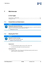
Page 35: ...optimum alignment of mechanical components and piezo actuators Do not open the P 545 7 2 Cleaning the P 545 NOTICE Damage from ultrasonic cleaning Ultrasonic cleaning can damage the P 545 Do not do an...

Page 36: ......

Page 37: ...ose of the P 545 e g surface made of aluminum Mount loads onto the P 545 with the following characteristics only The contact surface of the load has a flatness of at least 100 m The thermal expansion...

Page 38: ......

Page 39: ...tion Product and serial numbers of all products in the system Firmware version of the controller if applicable Version of the driver or the software if applicable Operating system on the PC if applica...

Page 40: ......

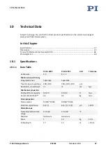
Page 41: ...P 545 3C8S Unit Tolerance Active axes X Y X Y Z Motion and positioning Integrated sensor Capacitive Capacitive Travel range closed loop 200 200 200 200 200 m Resolution closed loop 1 1 nm typ Mechanic...

Page 42: ...by the noise of the amplifier and the measuring technology because PI piezo nanopositioning systems are free of friction For dynamic operation Higher dynamics are possible with a reduced load All spe...

Page 43: ...f the system is limited only by the noise of the amplifier and the measuring technology because PI piezo nanopositioning systems are free of friction For dynamic operation Higher dynamics are possible...

Page 44: ...ause PI piezo nanopositioning systems are free of friction For dynamic operation Higher dynamics are possible with a reduced load All specifications based on room temperature 22 C 3 C 10 1 2 Maximum R...

Page 45: ...indoor use only Maximum altitude 2000 m Air pressure 1100 hPa to 0 1 hPa Relative humidity Highest relative humidity 80 for temperatures up to 31 C Decreasing linearly to 50 relative humidity at 40 C...

Page 46: ...s in mm Note that the decimal points are separated by a comma in the drawings Figure 13 P 545 1 Upper mounting surface of the motion platform with eight M2 5 mounting holes 2 Lower mounting surface of...

Page 47: ...545 Nanopositioners PZ272E Version 1 1 0 43 10 2 2 P 545 SH4 Microscope Slide and Petri Dish Holder Figure 14 P 545 SH4 Microscope slide and Petri dish holder for P 545 PInano piezo system with U 780...

Page 48: ...44 Version 1 1 0 PZ272E P 545 Nanopositioners 10 2 3 P 545 SH3 Microscope Slide Holder Figure 15 P 545 SH3 Microscope slide holder suitable for PInano piezo stages 1 Recess for standard microscope sl...

Page 49: ...on 1 1 0 45 10 2 4 P 545 PD3 Petri Dish Holder Figure 16 P 545 PD3 Petri dish holder suitable for PInano piezo stages 10 2 5 P 545 PP3 Universal Holding Plate Figure 17 P 545 PP3 Universal holding pla...

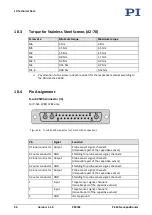
Page 50: ...onnections Pin Signal Function A1 inner conductor Output Probe sensor signal channel 2 immovable part of the capacitive sensor A1 outer conductor GND Shielding for probe sensor signal channel 2 A2 inn...

Page 51: ...GND Shielding for target sensor signal channel 3 14 not connected 15 not connected 16 not connected 17 not connected 18 not connected 19 Input Piezo voltage channel 3 20 Input Piezo voltage channel 2...

Page 52: ...2 GND Ground 3 Free 4 Free 5 Free 6 Free 7 GND Ground 8 Output SGS 3 signal 9 GND Ground 10 Output SGS 2 signal 11 GND Ground 12 Output SGS 1 signal 13 GND Ground 14 Free 15 Free 16 Input Piezo volta...

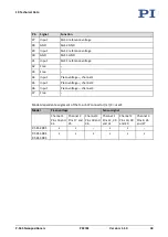
Page 53: ...e 33 Free 34 Input Piezo voltage channel 1 35 Input Piezo voltage channel 2 36 Input Piezo voltage channel 3 37 Free Model dependent assignment of the D sub 37 connector m X used Model Piezo voltage S...

Page 54: ......

Page 55: ...ational national and local rules and regulations In order to fulfil its responsibility as the product manufacturer Physik Instrumente PI GmbH Co KG undertakes environmentally correct disposal of all o...

Page 56: ......

Page 57: ...of conformity were issued according to the following European statutory requirements Low Voltage Directive EMC Directive RoHS Directive The standards applied for certifying conformity are listed below...

Reviews: