10 Technical Data
P-545 Nanopositioners
PZ272E
Version: 1.1.0
47
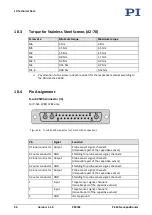
Pin
Signal
Function
4
Bidirectional
Data line for ID chip
5
---
(not connected)
6
---
(not connected)
7
---
(not connected)
8
Input
Piezo v, channel 3
9
Input
Piezo v, channel 2
10
Input
Piezo v, channel 1
11
Input
Target sensor signal, channel 1
(movable part of the capacitive sensor)
12
GND
Shielding for target sensor signal, channel 2
13
GND
Shielding for target sensor signal, channel 3
14
---
(not connected)
15
---
(not connected)
16
---
(not connected)
17
---
(not connected)
18
---
(not connected)
19
Input
Piezo voltage –, channel 3
20
Input
Piezo voltage –, channel 2
21
Input
Piezo voltage –, channel 1
22
GND
Shielding for target sensor signal, channel 1
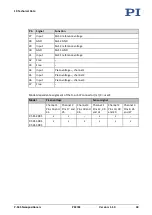
Model-dependent assignment of the D-sub 25W3 connector (m) (X = used):
Model
Piezo voltage
Sensor signal
(Probe / Target / shield)
Channel 1
Pins 10 and
21
Channel 2
Pins 9 and
20
Channel 3
Pins 8 and
19
Channel 1
Pins A3, 11
and 22
Channel 2
Pins A1, 1
and 12
Channel 3
Pins A2, 2
and 13
P-545.2C8S
X
X
–
X
X
–
P-545.3C8S
X
X
X
X
X
X


