10 Technical Data
46
Version: 1.1.0
PZ272E
P-545 Nanopositioners
10.3
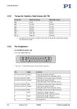
Torque for Stainless Steel Screws (A2-70)
Screw size
Minimum torque
Maximum torque
M6
4 Nm
6 Nm
M5
2.5 Nm
3.5 Nm
M4
1.5 Nm
2.5 Nm
M3
0.8 Nm
1.1 Nm
M2.5
0.3 Nm
0.4 Nm
M2
0.15 Nm
0.2 Nm
M1.6
0.06 Nm
0.12 Nm
Pay attention to the screw-in depth required for the respective material according to
the VDI directive 2230.
10.4
Pin Assignment
D-sub 25W3 connector (m)
For P-545.2C8S/.3C8S only:
Figure 18: D-sub 25W3 connector (m): Front with connections
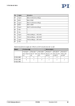
Pin
Signal
Function
A1 inner conductor Output
Probe sensor signal, channel 2
(immovable part of the capacitive sensor)
A1 outer conductor GND
Shielding for probe sensor signal, channel 2
A2 inner conductor Output
Probe sensor signal, channel 3
(immovable part of the capacitive sensor)
A2 outer conductor GND
Shielding for probe sensor signal, channel 3
A3 inner conductor Output
Probe sensor signal, channel 1
(immovable part of the capacitive sensor)
A3 outer conductor GND
Shielding for probe sensor signal, channel 1
1
Input
Target sensor signal, channel 2
(movable part of the capacitive sensor)
2
Input
Target sensor signal, channel 3
(movable part of the capacitive sensor)
3
GND
ID chip ground


