6
Installation
6.1
Mounting the V-417.xx6025E0
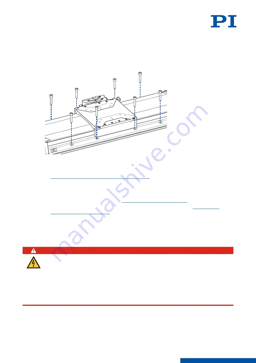
Overview
Figure 5: Mounting the V-417.xx6025E0 onto an underlying surface
Tools and Accessories
■
Screw set for mounting the V-417.xx6025E0 (p. 9)
■
Suitable screwdriver
Requirements
✓
You have read and understood the
general safety instructions (p. 7)
✓
You have provided a suitable surface with the holes necessary for the
required, locating pins (p. 28)
■
The flatness of the surface is
≤
2 μm.
■
For applications with large temperature changes: The surface should have the same or
similar thermal expansion properties as the V-417.xx6025E0.
✓
You have accounted for the space required to route cables without bending and
according to regulations.
DANGER
Risk of electric shock if the protective earth conductor is not connected!
If the protective earth conductor is missing or not properly connected, risk of dangerous
touch voltages on the V-417.xx6025E0 in the event of malfunction or failure of the system. If
there are touch voltages, touching the V-417.xx6025E0 leads to serious injuries or death by
electric shock.
►
Connect the V-417.xx6025E0 to a protective earth conductor before startup.
►
Do not remove the protective earth conductor during operation.
►
If the protective earth conductor has to be removed temporarily (e.g., for modifications),
reconnect the V-417.xx6025E0 to the protective earth conductor before restarting.
6 INSTALLATION
V417M0010EN
‒
4/26/2019
13
M O T I O N | P O S I T I O N I N G


