Requirements
✓
You have read and understood the
general safety instructions (p. 7)
✓
You have mounted the V-417.xx6025E0
properly.
✓
The V-417.xx6025E0 is not connected to the electronics.
✓
You have prepared the load so that it can be fixed to the mounting holes on the motion
platform:
■
The distance between the center of gravity of the load and the center of the motion
platform is as small as possible in all directions.
■
At least three points are provided for fixing the load on the motion platform.
NOTICE
Impermissibly high load on the V-417.xx6025E0
An impermissible high load impairs the motion of the platform and can damage the
V-417.xx6025E0.
►
Pay attention to the
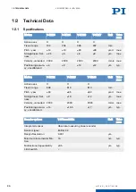
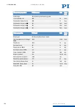
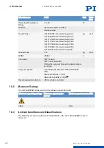
maximum permissible forces (p. 25)
that may act on the motion
platform.
►
In the case of multi-axis systems, include the masses of the positioners to be moved
when calculating the load.
NOTICE
Excessively long screws and locating pins
Screws and locating pins that are inserted too deeply can damage the V-417.xx6025E0.
►
Pay attention to the
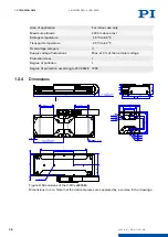
depth of the mounting and locating holes (p. 29)
►
Only use screws and locating pins of the correct length for the respective mounting holes.
Fixing the Load
1. If necessary: Insert the locating pins into the corresponding holes in the motion platform.
2. Align the load on the motion platform so that the mounting holes selected in the motion
platform can be used for mounting the load.
3. Place the load onto the motion platform so that the locating pins are inserted into the
corresponding locating holes in the load.
4. Tighten the screws in all mounting holes.
5. Check that the load is fixed firmly to the motion platform.
6.5
Connecting the V-417.xx6025E0
Tools and Accessories
■
Suitable cable set
■
If necessary: Suitable screwdriver for the locking screws of the connectors.
■
Optional: Purge air connector with the following properties:
Pressure: 2 to 6 bar (200 to 600 kPa); purge air hose: Outer diameter 4 mm; air quality as
stated in the
Requirements
✓
You have read and understood the
general safety instructions (p. 7)
✓
You have read and understood the user manual for the electronics.
✓
You have installed the electronics properly.
✓
The electronics are switched off.
✓
The V-417.xx6025E0 is connected to the
protective earth conductor (p. 14)
.
6 INSTALLATION
V417M0010EN
‒
4/26/2019
17
M O T I O N | P O S I T I O N I N G


