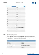
14.1.2 Encoder connector
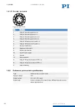
Figure 12: M17 15 (f)
Pin
Function
1
Output: Encoder signal sine (+)
2
Output: Encoder signal sine (-)
3
Output: Encoder signal cosine (+)
4
Output: Encoder signal cosine (-)
5
Output: Reference point switch (+)
6
Output: Reference point switch (-)
7
Service: Calibration
8
Negative limit switch
9
Positive limit switch
10
Input: Power supply
11
Ground
12
Not connected
A
Output: Temperature sensor (PTC) (+)
B
Output: Temperature sensor (PTC) (-)
C
Outer shielding
14.2
Reference point switch specifications
Type
Optical sensor, encoder index
Supply voltage
+5 V
Signal output
0 V / +5 V (TTL level)
Signal logic
Index in middle of the travel range, differential pulse via one
sensor signal period.
14 APPENDIX
V417M0009EN
‒
4/26/2019
32
M O T I O N | P O S I T I O N I N G

