background image

Summary of Contents for V-273

Page 1: ...mail info pi ws MP124E V 273 VC Linear Actuator User Manual Version 1 0 0 Date 30 03 2015 This document describes the following products V 273 430 PIMag Voice Coil Linear Actuator 20 mm 6 N Linear Enc...

Page 2: ...rumente PI GmbH Co KG Karlsruhe Germany The text photographs and drawings in this manual are protected by copyright With regard thereto Physik Instrumente PI GmbH Co KG retains all the rights Use of s...

Page 3: ...2 Safety 5 2 1 Intended Use 5 2 2 General Safety Instructions 5 2 3 Organizational Measures 6 3 Product Description 7 3 1 Model Overview 7 3 2 Product View 7 3 2 1 Overview 7 3 2 2 Product Details 8 3...

Page 4: ...ontroller 24 7 Maintenance 27 7 1 General Notes on Maintenance 27 7 2 Cleaning the V 273 27 8 Troubleshooting 29 9 Customer Service 31 10 Technical Data 33 10 1 Specifications 33 10 1 1 Data Table 33...

Page 5: ...that the reader has a fundamental understanding of basic servo systems as well as motion control concepts and applicable safety procedures The latest versions of the user manuals are available for do...

Page 6: ...The V 273 thus combines a relatively long travel range with a high velocity and a high resolution Max push pull force Maximum force in the direction of motion Position or velocity control When a coun...

Page 7: ...d 1 4 Figures For better understandability the colors proportions and degree of detail in illustrations can deviate from the actual circumstances Photographic illustrations may also differ and must no...

Page 8: ...able manuals are displayed 5 Click the desired manual and save it on the hard disk of your PC or on a data storage medium Download password protected manuals 1 Insert the product CD in the PC drive 2...

Page 9: ...or handling technology The V 273 is not intended for applications in areas in which a failure would present severe risks to human beings or the environment The intended use of the V 273 is only possi...

Page 10: ...If you pass the V 273 on to other users also turn over this user manual as well as other relevant information provided by the manufacturer Only use the device on the basis of the complete user manual...

Page 11: ...Two standard versions of the V 273 linear actuator are available They differ with regard to the force sensor and thus the dimensions Model Dimension Force sensor present V 273 430 200 mm x 51 mm x 37...

Page 12: ...guide rail 2 Case 3 Connection for motor cable panel plug Sub D 15 x Positive direction of motion Figure 3 Front side of the V 273 431 linear actuator 1 Cable exit of the force sensor 2 Exchangeable c...

Page 13: ...ear side of the V 273 linear actuator hole pattern and transport lock are identical for both standard versions 1 Case 2 Transport lock M2 5 screw 3 2 3 Product Labeling On the case of the V 273 there...

Page 14: ...9 consecutive numbers Manufacturer s logo Warning sign Observe manual Old equipment disposal p 43 Country of origin Germany Country of origin WWW PI WS Manufacturer s address website CE conformity mar...

Page 15: ...ntrollers is described in the corresponding user manuals 3 5 Technical Features 3 5 1 Linear Encoder The V 273 is equipped with an optical linear encoder For the resolution refer to the table in the S...

Page 16: ...When the controller is switched on or rebooted the connected force sensor always measures 0 N regardless of the actual force exerted on the force sensor 3 5 4 ID Chip The V 273 linear actuators contai...

Page 17: ...he V 273 as well as cause accuracy losses Only ship the V 273 in the original packaging and with a transport lock installed Only hold the V 273 by the housing The V 273 is delivered with a transport l...

Page 18: ...against the packing list If parts are incorrectly supplied or missing contact PI immediately 3 Inspect the contents for signs of damage If you notice signs of damage contact PI immediately 4 Remove th...

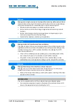
Page 19: ...sipated heat Ensure sufficient ventilation at the place of installation Make sure that the complete bottom side of the V 273 is in contact with the surface on which the V 273 is mounted NOTICE Lubrica...

Page 20: ...contact piece made of aluminum and plastic is installed by default If you change the contact piece you may have to adapt the parameter settings of the C 413 controller to the changed contact stiffnes...

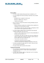
Page 21: ...s the motion of the rod and increases the wear of the drive components Avoid lateral forces on the rod of the V 273 NOTICE Screws that are too long Screws that are inserted too deeply damage the V 273...

Page 22: ...tuator using screws Figure 7 V 273 430 The white arrows mark the holes for affixing the movable part of the mounting to the rod Figure 8 V 273 430 Mounting holes for attaching the V 273 to a surface i...

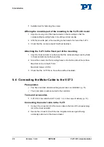
Page 23: ...mechanical mounting for attaching the case of the V 273 At least three M4 mounting holes are present For the required position of the holes see Dimensions p 37 The thickness of the surface the depth o...

Page 24: ...ng holes in linear actuator and surface overlap 2 Screw the screws into the mounting holes on the bottom side of the surface Maximum screw in depth 5 mm Maximum torque 2 6 Nm 3 Check that the V 273 fi...

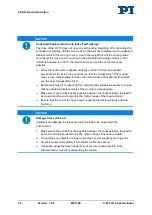
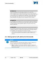
Page 25: ...your application Ensure sufficient ventilation at the place of installation Ensure that the average continuous current and the peak current do not exceed the permissible values p 33 NOTICE Operating...

Page 26: ...f For details see the user manual of the C 413 Before switching off or rebooting the controller take suitable measures to ensure that no undesired displacements of the moving rod are possible Make sur...

Page 27: ...oved mass Unsuitable servo control parameter settings of the controller can cause the V 273 to oscillate Oscillations can damage the V 273 and or the load affixed to it If the V 273 is oscillating unu...

Page 28: ...m PI fulfill this requirement with their automatic direction detection for reference moves to the reference point switch INFORMATION The force sensor of the V 273 431 model works as an incremental sen...

Page 29: ...e assigned to axis 2 via the Input Channel for Force Feedback parameter ID 0x07000400 Prerequisites You have read and understood the General Notes on Start Up You have read and understood the user man...

Page 30: ...ersion 1 0 0 MP124E V 273 VC Linear Actuator Commanding initial motions in closed loop operation for testing the mechanical system In the user manual of the C 413 controller the start up is described...

Page 31: ...73 is maintenance free Opening the case causes damage to the V 273 Only loosen screws according to the instructions in this manual Do not open the V 273 7 2 Cleaning the V 273 Prerequisites You have d...

Page 32: ......

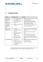
Page 33: ...Warped case Excessive lateral forces on the rod Excessive torque on the rod when the load is mounted Velocity too high Moving with maximum force to the hard stop Mount the V 273 on an even surface The...

Page 34: ......

Page 35: ...uestions concerning your system have the following information ready Product codes and serial numbers of all products in the system Firmware version of the controller if present Version of the driver...

Page 36: ......

Page 37: ...sensor Optical linear encoder Open loop position resolution 10 nm typ Closed loop position resolution 100 nm typ Open loop force resolution 0 001 N typ Closed loop force resolution 0 02 N typ Linearit...

Page 38: ...0 125 A N typ Average continuous current 400 mA max Peak current max 3 s 800 mA Average push pull force 3 N nominal Power dissipation with 100 duty cycle 2 25 W Maximum push pull force 6 N max Power...

Page 39: ...nditions and classifications must be observed for the V 273 Area of application For indoor use only Maximum altitude 2000 m Air pressure 1100 hPa to 795 hPa corresponds to roughly 825 Torr to 596 Torr...

Page 40: ...ions Type Optical sensor Supply voltage 5 V GND supply via the motor connector Signal output TTL level Signal logic Direction sensing by means of different signal levels on the left and right side of...

Page 41: ...near Actuator MP124E Version 1 0 0 37 10 2 Dimensions 10 2 1 V 273 430 Dimensions in mm Note that the decimal places are separated by a comma in the drawings Figure 10 Dimensions of the V 273 430 movi...

Page 42: ...sions in mm Note that the decimal places are separated by a comma in the drawings Figure 11 Dimensions of the V 273 431 here without contact piece of the force sensor moving rod in reference position...

Page 43: ...10 Technical Data V 273 VC Linear Actuator MP124E Version 1 0 0 39 Figure 12 Dimensions of the V 273 431 here with contact piece of the force sensor moving rod in reference position...

Page 44: ...ure 13 Sub D 15 m panel plug Pin Function Direction 1 2 Motor Input current 3 AGND GND 4 VDD 5 V Input 5 6 SPI_CS_EEPROM TTL input 7 SPI_MOSI TTL input 8 SPI_MISO TTL output 9 Motor Input current 10 A...

Page 45: ...nsor Sub D 15 m connector Figure 14 Sub D 15 m connector Pin Function Direction 1 2 3 GND GND 4 VDD 5 V Input 5 6 SPI_CS_EEPROM TTL input 7 SPI_MOSI TTL input 8 SPI_MISO TTL output 9 10 11 12 13 14 SP...

Page 46: ......

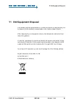
Page 47: ...international national and local rules and regulations To meet the manufacturer s product responsibility with regard to this product Physik Instrumente PI GmbH Co KG ensures environmentally correct di...

Page 48: ......

Page 49: ...claration of Conformity has been issued in accordance with the following European directives 2004 108 EC EMC Directive 2011 65 EU RoHS Directive The applied standards certifying the conformity are lis...

Reviews: