background image

Kenos

®

KCS Manual 

Page 26 of 34 

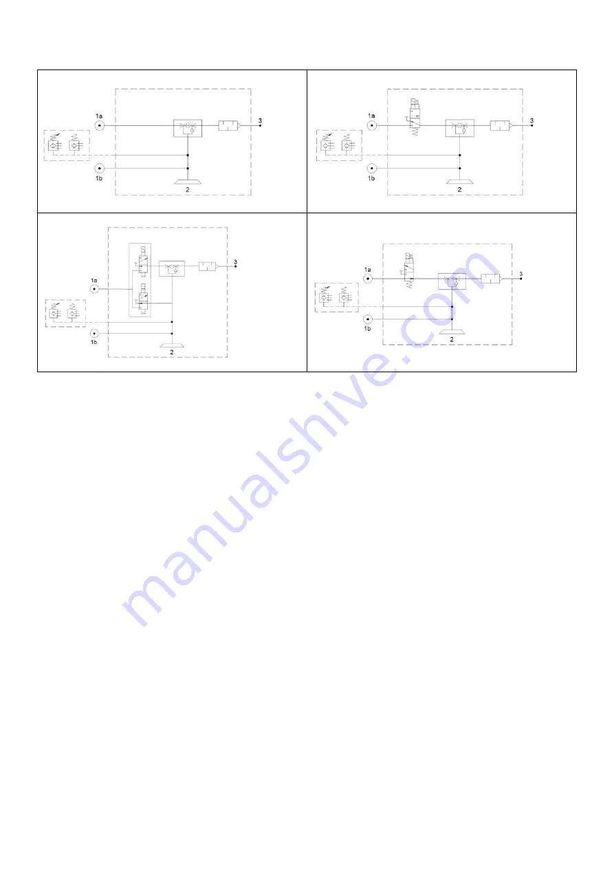
KCS.Q110.BC.EJECTOR.BASE 


KCS.Q110.BC.EJECTOR.V1 


KCS.Q110.BC.EJECTOR.V2 


KCS.Q110.BC.EJECTOR.V3 


1a = PRESSURE AIR SUPPLY FOR VACUUM 

1b = PRESSURE AIR SUPPLY FOR BLOW OFF 

2 = VACUUM 

3 = EXHAUST 


optional 

optional 

optional 

optional 

Summary of Contents for Kenos KCS Series

Page 1: ...Manual Kenos KCS Series www piab com ...

Page 2: ......

Page 3: ...m 25 Spare parts 27 Foam spare parts 27 Accessories 28 Cable specification 29 Warranties 31 Copyright protection This manual has the Use and Maintenance instructions for the vacuum gripping system and as such it must be treated with the utmost confidentiality It is intended exclusively for use by persons authorized in your company The transfer to third parties can only take place with the prior wr...

Page 4: ...al or pneumatic supply is interrupted to protect persons and systems Consider the emergency stop when designing the system Consider restarting the machine after an emergency stop and machine downtime in order to avoid the risk of injury to persons and or damage to the system The products in this manual are designed for implementation in industrial systems therefore they should not be used under ap...

Page 5: ...s with care During installation and maintenance cut off voltage and pressure Modifying the components is prohibited Cleaning the environment and place of use is recommended Follow the installation and commissioning instructions The electrical and pneumatic connections should be permanently connected to the component Storage For a correct storage of the incoming system or its spare parts we recomme...

Page 6: ...ence data of the same are indelibly marked For any communication with PIAB or service centers always quote these references Failure to comply with the above rules may cause malfunctions damage injury including with serious consequences Label position Note The position of the label on the system may vary depending on the model ...

Page 7: ...Manual Page 6 of 34 Overview Part list with flow reduction version Description A Pneumatic supply G1 8 connection for vacuum 1a B Pneumatic supply G 1 8 connection for blow off 1b C Pump unit D Foam gripper unit ...

Page 8: ...Kenos KCS Manual Page 7 of 34 Part list with bag cup version Description A Pneumatic supply G1 8 connection for vacuum 1a B Pneumatic supply G 1 8 connection for blow off 1b C Pump unit D Bag cup unit ...

Page 9: ...ow off if necessary N B In this case the activation for vacuum can be done before or after the contact with the workpiece Note We recommend always running preliminary tests with original samples We are able to perform these tests for you Stopping or passing through the work area of the gripper module is prohibited as in case of electrical or pneumatic supply failure the load handled by the module ...

Page 10: ...nos KCS Manual Page 9 of 34 Installation Mounting on the adapter system The pump unit is mounted on the special adapter system Pos Description A Special adapter system B Pump unit C Adapter fixing screws ...

Page 11: ...and the gripper modules are connected by a quick change system Attention the point 1 need to be aligned with the indication B Pos Description A Quick change system B Metal threaded insert for quick change system locking C Pump unit D Bag cup unit E Foam gripper unit ...

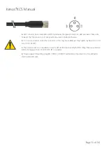
Page 12: ...nector M8 3 pin male Specifications for solenoid valves Fluid Air Operating pressure range MPa psi 0 15 0 7 22 87psi Operating temperature C F 10 50 14 122 Manual override Push locking slotted style Lubrication Not required Impact Vibration resistance m s 150 30 Electrical connection Connector M8 3 pin male Coil rated voltage Vcc 24 Allowable voltage 10 rated voltage Current consumption mA 17 Surg...

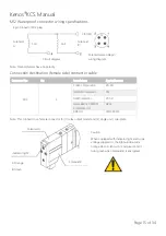
Page 13: ...when operating the locking type D with a screw driver turn it gently using a watchmakers screw driver Torque Less than 0 1 Nm 0 07 lbf With light surge voltage suppressor U Solenoid valve side pin wiring diagram for WA type Specifications for solenoid valve connector Number and section of conductors mm 3x0 25 Safety classification IP 67 External diameter mm in 4 1 0 16 Max curvature ray for flexin...

Page 14: ...ater Do not use a tool to mount the connector as this may cause damage Only tighten by hand 0 4 to 0 6 Nm 30 to 44 lbf The excessive stress on the cable connector will not be able to satisfy the IP65 rating Please use caution and do not apply a stress of 30 N 6 74 lbf or greater Torque couple of mounting screw M3 0 8 Nm 0 59 lbf Put attention at the direction of mounting for electro valve and seal...

Page 15: ...ations for solenoid valves Fluid Air Operating pressure range MPa psi 0 15 0 7 22 87psi Operating temperature C F 10 50 14 122 Manual override Push locking slotted style Lubrication Not required Impact Vibration resistance m s 150 30 Electrical connection M12 4 pin waterproof connector Male Coil rated voltage Vcc 24 Allowable voltage 10 rated voltage Current consumption mA 27 Surge voltage suppres...

Page 16: ...ble series M12 4 Correns Corporation VA 4D OMRON Corporation XS2 Azbil Corporation PA5 41 Hirose Electric OMRON Corporation Ltd HR24 DDK Ltd CM01 8DP4S Coil Coil 3 COM Solenoid valve side pin wiring diagram Circuit diagram Solenoid A Solenoid B Solenoid A Solenoid B Indicator light A Orange B Green Caution When equipped with indicator light and surge voltage suppressor the light window turns orang...

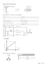
Page 17: ...on Operating humidity range Operating Stored 35 to 85 RH No condensation Withstand voltage 1000 V AC in 50 60 Hz for 1 minute between terminals and housing Insulation resistance 50 MΩ or more 500 V DC measured via megohmmeter between terminals and housing Temperature characteristics 2 F S 25 C reference Sensor cable Oilproof heavy duty vinyl cable ellipse 3 cores 2 7 x 3 2 conductor area 0 15 mm2 ...

Page 18: ...nector Port size Ø 4 reducer Case PBT Pressure sensing section Silicon O ring NBR Max curvature ray for flexing use 10 x external diameter Case PUR UL CSA Connections 3 Blue 4 Black 1 Brown A Ø 4 mm B 18 mm Analog output Blue DC Brown DC Load Main circuit MALE Black out Pressure Analog output ...

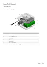
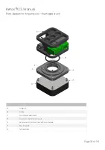
Page 19: ... Parts diagram Parts diagram for pump unit Pos Description A Plastic basic body B Ejector piCHIP SX42 or SX12 C Solenoid valve D Silencer E Vacuum sensor F M8 3 pin male connector G Metal threaded insert for quick change system lock ...

Page 20: ...Kenos KCS Manual Page 19 of 34 Parts diagram for pump unit and bag cup unit Pos Description A Pump unit B X Ring C Bag cup plastic body D Screw for connection to pump unit ...

Page 21: ...ts diagram for for pump unit foam gripper unit Pos Description A Pump unit B X Ring C Foam gripper plastic body D Screw for connection to pump unit E Fixing Screws for technical foam with mounting plate F Mounting plate G Technical foam ...

Page 22: ... foam Clean the metal plate from any adhesive and dust residues e g with solvent Attention Be careful that the holes are not blocked by any kind of residue if they are clean them Remove the silicon paper from the foam Align the holes on the metal plate and on the foam Fix the new foam on metal plate Attention Prevent formation of channels they must be avoided Press the new foam To store the foam T...

Page 23: ...ry 6 months Every 12 months Check Max vacuum level of the ejector Check the micro holes Check the silencer Check tightening s Check the foam Check supply air pressure Check the electrical connection Check the air connection Check the general condition Clean gripper exterior ...

Page 24: ...t not gripped Low vacuum level See above Insufficient suction capacity change the ejector version Dirty micro holes Clean Lift is too fast Slow down lift avoid acceleration peaks Pieces not suitable for lift with this system Replace grip solution Occluded foam filter with filter version Clean Occluded silencer Replace silencer Foam wears very quickly The system is not corrected placed on the workp...

Page 25: ...riprtion Unit SX42 ejector with 1 2 cartridge Feed pressure optimal MPa 0 5 Max vacuum at opt pressure kPa 90 Air consumption at opt pressure cartridge Nl s 2 21 Max vacuum flow at opt pressure cartridge Nl s 3 46 Descriprtion Unit SX42 ejector with 1 2 cartridge Feed pressure optimal MPa 0 5 Max vacuum at opt pressure kPa 85 Air consumption at opt pressure cartridge Nl s 0 72 Max vacuum flow at o...

Page 26: ...FR SERIES PNEUMATIC DIAGRAM KCS Q110 NXXX FR EJECTOR BASE KCS Q110 NXXX FR EJECTOR V1 KCS Q110 NXXX FR EJECTOR V2 KCS Q110 NXXX FR EJECTOR V3 1a PRESSURE AIR SUPPLY FOR VACUUM 1b PRESSURE AIR SUPPLY FOR BLOW OFF 2 VACUUM 3 EXHAUST Only for foam with filter version Only for foam with filter version optional optional optional Only for foam with filter version Only for foam with filter version option...

Page 27: ... of 34 KCS Q110 BC EJECTOR BASE KCS Q110 BC EJECTOR V1 KCS Q110 BC EJECTOR V2 KCS Q110 BC EJECTOR V3 1a PRESSURE AIR SUPPLY FOR VACUUM 1b PRESSURE AIR SUPPLY FOR BLOW OFF 2 VACUUM 3 EXHAUST optional optional optional optional ...

Page 28: ...09259 Solenoid valve EV 3 2 N C 0211614 Solenoid valve EV 2x3 2 N C N C 0211305 Solenoid valve EV 3 2 N O 0212157 X RING 228 56 74 x 3 53 5PZ Foam spare parts If you are unsure which spare part you need please check the part code of your configured KCS product the first part of the product code is reused in the foam spare part code when you put FOAM in front see below KCS product code KCS Q110 N30...

Page 29: ... V1 V3 MA 250mm Yellow Monitoring connection Black Solenoid valve connection Art No Description 0108141 Cable M8 3 pin female L 2m 0121817 Cable M12 4 pin female L 5m Analog vacuum switch PSE541 R04 3 Poles female connector Solenoid valve SYJ 3 Poles female connector Black analog output Blue GND Brown 24V Rethink M12 8 Poles Male connector Black analog input Blue GND Brown 24V Blue GND2 Brown digi...

Page 30: ...ection Analog vacuum switch PSE541 R04 3 poles female connector Black analog output Blue GND White Analog input UR M8 8 POLES FEMALE CONNECTOR Solenoid valve SYJ 3 Poles female connector Brown 24 V Red GND Pink NPN Digital output Gray 24 V Solenoid valve SYJ 3 Poles female connector Digital vacuum switch PNP NO LM8 3 Poles female connector Black digital input Blue GND1 Brown 24V Blue GND2 Brown di...

Page 31: ...Kenos KCS Manual Page 30 of 34 Art No Description 0212281 Y cable UR KCS M8 8p V1 V3 MA 250mm ...

Page 32: ...trol or maintenance contrary to any applicable manual or instructions for the Products issued by the Seller or good trade practice regarding the same or b has been reconstructed repaired or altered by any persons or entities other than the Seller or its authorized representatives or have a defect as a result of fair wear and tear or wilful damage or caused by subsequent damages caused by other def...

Page 33: ...Kenos KCS Manual Page 32 of 34 ...

Page 34: ... piab com ITALY Torino Phone 39 011 226 36 66 Email info italy piab com JAPAN Tokyo Phone 81 3 6662 8118 Email info japan piab com POLAND Gdansk Phone 48 58 785 08 50 Email info poland piab com SPAIN Barcelona Phone 34 93 6333876 Email info spain piab com SINGAPORE Phone 65 6455 7006 Email info singapore piab com SWEDEN Stockholm HQ Phone 46 8 630 25 00 Email info sweden piab com SWEDEN Mölndal Er...

Reviews: