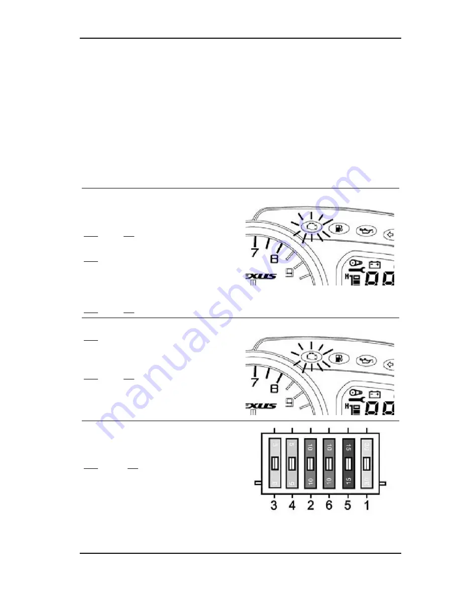
Constant supply circuit check
The decoder basic power supply is necessary for the deterrent flashing management. The injection
control unit power supply is necessary for the Stepper motor management.
A power supply failure disables both ignition and injection.
In case of power supply faults, the diagnostic tester gives the information "NO REPLY FROM THE
CONTROL UNIT".
To carry out the check, proceed as follows:
Specific tooling
020680Y
Diagnosis Tool
1
- Check whether the immobiliser system LED in-
dicates that the switch is in position "
ON
" and that
the deterrent flashing is on.
YES go to 2 NO go to 7
2
- The decoder is properly programmed.
YES go to 3
3
- Switch set to "
ON
" with side stand raised and
emergency switch set to "
OFF
". The injection tell-
tale light turns on for about 3 seconds.
YES go to 5 NO go to 4
4
- Check the instrument unit and its power supply.
YES go to 3
5
- Set the emergency switch to "
RUN
". The injec-
tion telltale light comes on for about 5 seconds.
YES go to 6 NO go to 7
6
- The injection controller is certainly powered.
7
- Check the efficiency of the 3 A fuse no. 3 loca-
ted in the fuse-holder under the right side.
YES go to 10 NO go to 8
Beverly 500 i.e.
Injection
INJEC - 181
Summary of Contents for Beverly 500 i.e.
Page 1: ...WORKSHOP MANUAL 633387 Beverly 500 i e...
Page 5: ...INDEX OF TOPICS CHARACTERISTICS CHAR...
Page 17: ...INDEX OF TOPICS MAINTENANCE MAIN...
Page 32: ...INDEX OF TOPICS ELECTRICAL SYSTEM ELE SYS...
Page 51: ...INDEX OF TOPICS ENGINE FROM VEHICLE ENG VE...
Page 54: ...INDEX OF TOPICS ENGINE ENG...
Page 162: ...Countershaft fixing nut 25 29 Engine Beverly 500 i e ENG 162...
Page 163: ...INDEX OF TOPICS INJECTION INJEC...
Page 260: ...INDEX OF TOPICS SUSPENSIONS SUSP...
Page 284: ...INDEX OF TOPICS BRAKING SYSTEM BRAK SYS...
Page 301: ...INDEX OF TOPICS COOLING SYSTEM COOL SYS...
Page 310: ...INDEX OF TOPICS CHASSIS CHAS...
Page 329: ...INDEX OF TOPICS PRE DELIVERY PRE DE...
Page 333: ...INDEX OF TOPICS TIME TIME...


