N.B.
TO ACCESS THE COMPONENTS, SEE THE COMPONENTS LAYOUT CHAPTER.
Specific tooling
020481Y
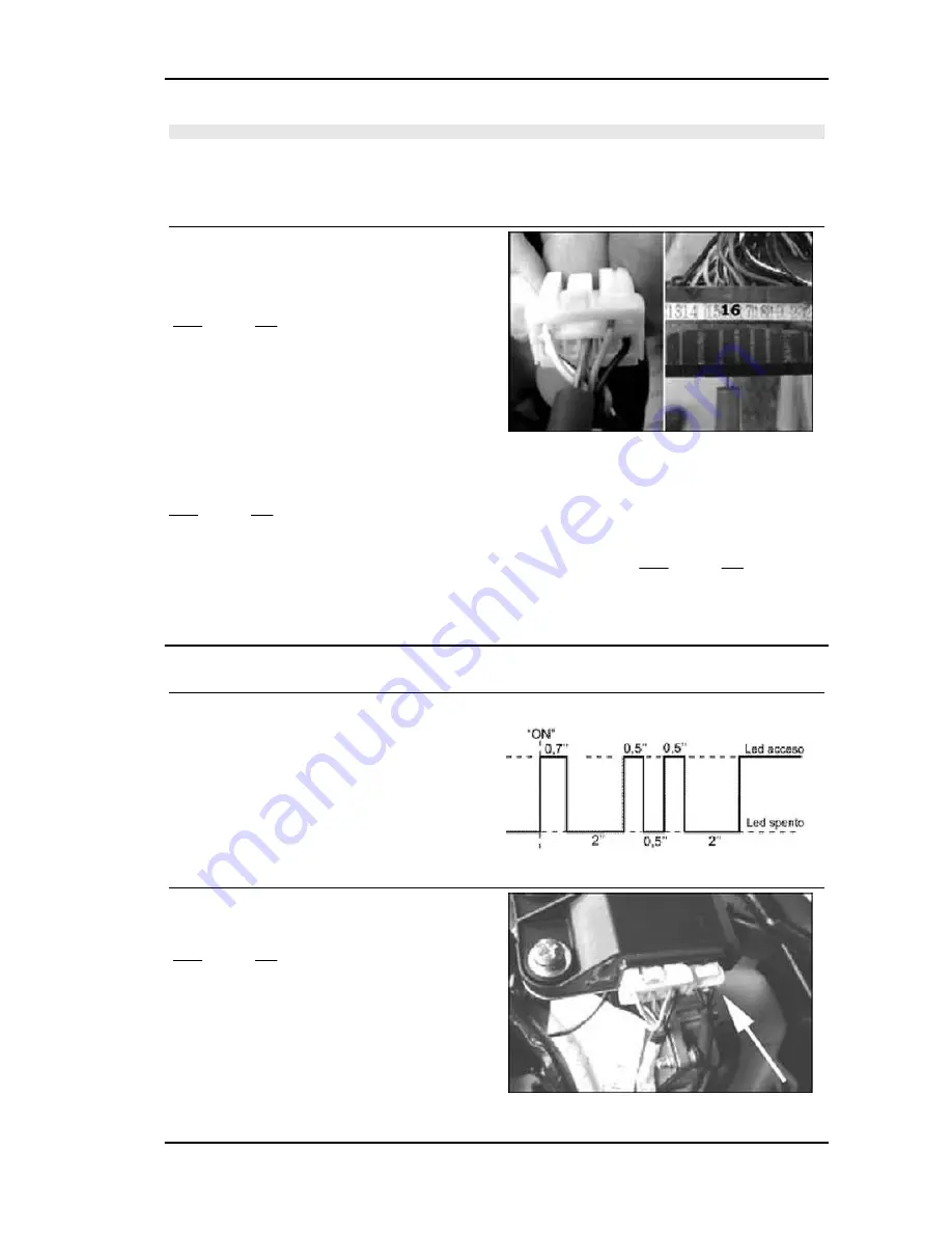
Control unit interface wiring
1
- Using a multimeter, check the continuity be-
tween pin 16 of the control unit and pin 6 of the
decoder connector.
YES go to 3 NO go to 2
2
- Repair or replace the wiring.
3
- Check the connections carefully
YES go to 5 NO go to 4
4
- Restore
5
- Replace the decoder. Connect the battery. Repeat the programming. YES go to 7 NO go to 6
6
- Disconnect the battery, replace the control unit, connect the battery. Repeat the programming.
7
- The system is OK
Code 2
Code no. 2 denotes a system where the decoder
does not perceive the transponder signal.
- Start-up disabled
- Injection telltale light on, steady
In this case, proceed as follows:
1
- Check whether the code is repeated using the
second key.
YES go to 3 NO go to 2
2
- Failure detected with the service key Replace
and program again. Failure detected with the mas-
ter key.
Replace the transponder using one from the new
cylinder kit.
Replace decoder and control unit.
Beverly 500 i.e.
Injection
INJEC - 221
Summary of Contents for Beverly 500 i.e.
Page 1: ...WORKSHOP MANUAL 633387 Beverly 500 i e...
Page 5: ...INDEX OF TOPICS CHARACTERISTICS CHAR...
Page 17: ...INDEX OF TOPICS MAINTENANCE MAIN...
Page 32: ...INDEX OF TOPICS ELECTRICAL SYSTEM ELE SYS...
Page 51: ...INDEX OF TOPICS ENGINE FROM VEHICLE ENG VE...
Page 54: ...INDEX OF TOPICS ENGINE ENG...
Page 162: ...Countershaft fixing nut 25 29 Engine Beverly 500 i e ENG 162...
Page 163: ...INDEX OF TOPICS INJECTION INJEC...
Page 260: ...INDEX OF TOPICS SUSPENSIONS SUSP...
Page 284: ...INDEX OF TOPICS BRAKING SYSTEM BRAK SYS...
Page 301: ...INDEX OF TOPICS COOLING SYSTEM COOL SYS...
Page 310: ...INDEX OF TOPICS CHASSIS CHAS...
Page 329: ...INDEX OF TOPICS PRE DELIVERY PRE DE...
Page 333: ...INDEX OF TOPICS TIME TIME...


