8
- Check for positive battery voltage on the red/
black cable of the 8-way connector of the instru-
ment panel.
YES go to 9 NO go to 10
9
- Faulty led, replace the instrument panel.
10
- Repair or replace the wiring.
11
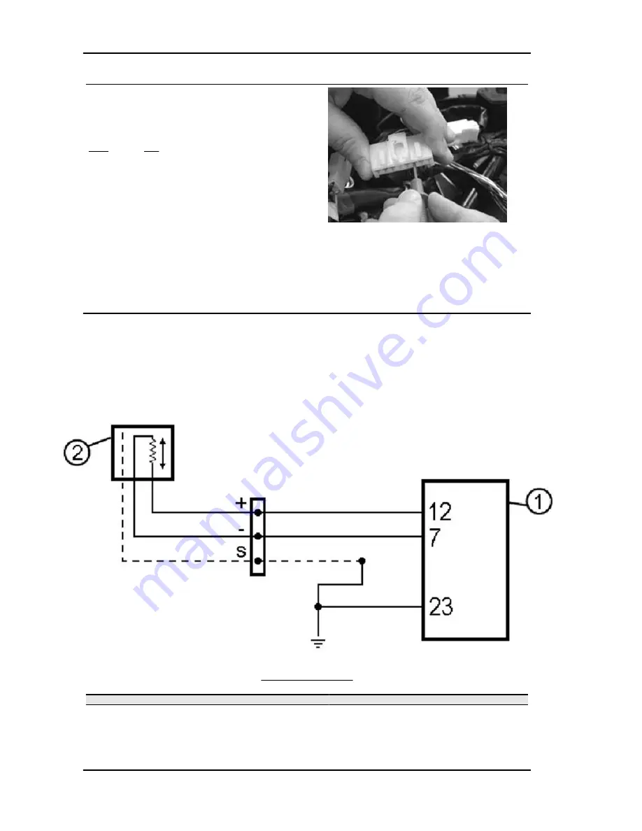
- If the injection light does not come on, continue with the check of the supply circuit to the decoder
and of the central control unit.
Tachometer
Electric characteristic
TERMINAL: 7 - 12
CONDITIONS :
Start-up speed
STANDARD:
approx. 0.8 - 4.5 V
CIRCUIT LAYOUT
Specification
Desc./Quantity
1
Electronic control unit
2
Engine Speed sensor
The sensor allows the rotations and the angular position of the crankshaft to be recognised by reference
to the TDC. Since the wheel speed sensor is pivoted on the camshaft it is also possible to recognise
Injection
Beverly 500 i.e.
INJEC - 224
Summary of Contents for Beverly 500 i.e.
Page 1: ...WORKSHOP MANUAL 633387 Beverly 500 i e...
Page 5: ...INDEX OF TOPICS CHARACTERISTICS CHAR...
Page 17: ...INDEX OF TOPICS MAINTENANCE MAIN...
Page 32: ...INDEX OF TOPICS ELECTRICAL SYSTEM ELE SYS...
Page 51: ...INDEX OF TOPICS ENGINE FROM VEHICLE ENG VE...
Page 54: ...INDEX OF TOPICS ENGINE ENG...
Page 162: ...Countershaft fixing nut 25 29 Engine Beverly 500 i e ENG 162...
Page 163: ...INDEX OF TOPICS INJECTION INJEC...
Page 260: ...INDEX OF TOPICS SUSPENSIONS SUSP...
Page 284: ...INDEX OF TOPICS BRAKING SYSTEM BRAK SYS...
Page 301: ...INDEX OF TOPICS COOLING SYSTEM COOL SYS...
Page 310: ...INDEX OF TOPICS CHASSIS CHAS...
Page 329: ...INDEX OF TOPICS PRE DELIVERY PRE DE...
Page 333: ...INDEX OF TOPICS TIME TIME...


