background image

Summary of Contents for Vespa Commercial

Page 1: ...1 C 1 HWd i j I J I SERVICE STATION MANUAL I 1 1 o...

Page 2: ...the following chapters Fault finding and remedies Tooling necessary for normal servicing operations Illustrations and instructions for stripping down overhauls and assembly Assel11bly play of main org...

Page 3: ...Ir 1 t J i 10 4 r I...

Page 4: ...ge Page 19 24 26 27 28 28 Assembly play between Con rod crankshaft Cylinder and piston Piston and wrist pin Con rod wrist pin Piston rings Gear box packing washers Hydraulic brake cylinder Rear wheel...

Page 5: ...rt 46 Engine Page 67 Inspection of rectifier 48 Engine timrng 72 Electric starter motor with description Differential 73 and illustration of the group 50 Wheel bracket 74 Carburettor description and t...

Page 6: ...ark advance For for mods AC 1 and AC 2 28 t 1 for Mod AC 3 25 t 1 Groups clutch gear change should be ac curately checked for play with respect to their relative cables see pages 38 39 and control lev...

Page 7: ...If the starter motor is installed in the case of battery inefficiences caused by irregularities or breakages in the charging circuit check fly wheel magneto and rectifier For starter motor see page 50...

Page 8: ...the case where normal adjustments are not sufficient in eliminating the fault inspect both the brake jaws and drums if exces sive wear or scratching is noted carry out the necessary substitutions If...

Page 9: ...noisy substitute worn or faulty components accordingly check the following points The spring if knocking occurs at the end of its run Efficiency of the front damper That the nuts on the wheel hub are...

Page 10: ...TO THAT PRE SCRIBED SPARKI NG PLUG NOT SUITABLE DEPOSIT BUILD UP WORN OR WITH INCORRECT GAP H T LEAD OR SPARK ING PLUG CAP WORN ENGINE WEAR NOISINESS i EA O CESSIVE QUAN I TITY Of OllaR Of OILWITH A D...

Page 11: ...713019 5 716050 6488 A 8290 R 4938 A I 5115 A T 12380 C 381500 8 381505 8 381510 8 Hand press Damper test bench Engine test bench 63 62 55 Flywheel mag test bench 37 Gauge Tool setting gauge Tool set...

Page 12: ...ush gear Bearing extractor for drive shaft jig for assembling lower race of steering column bottom bearing jig for removing bottom race of lower steering column bearing Pliers for removing circlips Di...

Page 13: ...ft 25 0018801 Chuck for reaming wheel bracket bush T OO18879 Tool for assy of wheel bracket bush 46 T 0018916 Work holder for substitution of main bearing bu 42 shes T 0019353 Box wrench for clutch se...

Page 14: ...er buffers and sleeve Tool for assy of buffer and sleeve on damper body Tool for assy of buffer and tube on stem support Tool for assy valve group to cylinder Drive shaft extractor Wrench for threaded...

Page 15: ...67 T 0018182 Extractor for crankshaft and differential bearings 21 26 T 0022480 Punch for extracting drive shaft bearing bush 41 T 0023278 Apparatus for engine timing 72 T 0023465 T 0016205 Graduated...

Page 16: ...tion and special operations which are not however indispensable for normal opns 13768 C T 0013460 T 0014208 15104 C 15120 C T 15648 C T 0021472 T 0023223 T 0023234 T 0024448 6698 A Vehicle mobile supp...

Page 17: ...tact breaker and spark gap Special screwdriver Extractor for rear wheel bushes Pliers for rear brake return spring Plunger for bleeding opn Tool securing cylinder to vice Tool for securing wheel cylin...

Page 18: ...rations which can be carried out using screwdriver wrenches pliers etc are not indicated We consider it advisable that the relative Spare Parts List be operations In s9much as it indicates in illustra...

Page 19: ...enches as indicated above for blo cking clutch retainer nut for clutches without crown wheel for vehicles without starter motor Fig 1 B Flywheel nut use the tool T 0021265 in cases of difficulty J C I...

Page 20: ...A s Fig 2 A Seperating crankcase halves Insert the wedge 1 0025127 so as to avoid deformation of crankshaft N B Suitably dispose a drip pan to collect the oil which will flow out c I B T 0014499 B Cra...

Page 21: ...STRIPPING DOWN Bearings and drive shaft Crankcase half clutch side A 8 T 0021 67 ID 00 M M 0 d d 0 E T 0015713 Fig 3 See instruction on following page 21...

Page 22: ...use plier 0023638 or similar standard tool B Crankshaft bearing if it remains in crankcase use component 7 of tool C Threaded ring securing bearing D Drive shaft group after having removed the gears...

Page 23: ...STRIPPING DOWN Oil seal Starter group Crankcase half flywheel side A Oil seal 0017843 oJ 1 B Fig 4 BJ Group starter first remove retainer ring 23...

Page 24: ...STRIPPING DOWN Wheel brackets c T 0018119 Part 11 of tool T 0014499 A F B 0018497 0 J part S of tool 10O208 G 1 0021272 H Fig 5 See opns on following page 24...

Page 25: ...cular slotted nut from central support first straigh ten the lugs on lock washer D Shock absorber pivot pins N B If the pin is not worn or rusted in its housing it can be extracted without the use of...

Page 26: ...or stripping down differential g Planetary housing C Bearing from housing cover STRIPPING DOWN f o V Om I T 0021467 B c 0 I I I I II r 1 I ParI 10 of tool 0 i 0 Fig 6 D Bearing from housing shank N g...

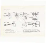
Page 27: ...lumn group c A B Upper bearing damper and bush unit C Track of lower steering column bearing I i t 0 1 I 1 1 T 0O14 99 Fig 7 E D E F Wheel axle hub and axle bearing G Upper track of lower steering col...

Page 28: ...s with harness removed to fa cilitate re assembly 3 Slide out gear change throttle and clutch cables from the handlebars 4 Withdraw cable harness inside chassis from under the steering column cover I...

Page 29: ...shaft gears cylinder and pistons for hydraulic brakes bronze liner bush on wheel brackets A CON ROD AND CRANKSHAFT E B F C Fig 8 29 Denomi Max play Pari name Normal dimensions nation of Assy play admi...

Page 30: ...ountersigned with the same letter II rebored the tollerances on the dimensions E must be maintained aoured along the plane of oscillation when the oversized piston is fitted to the cylinder the prescr...

Page 31: ...011 0 017 0 2 100 Wrist pin Q 15 0 009 P 15 0 005 normal 0 017 0 016 Part name Normal dimensions Play cI Max play on assy afler use Can rod G 15 0 005 normal 0 018 Wrist pin H 15 0 009 normal 0 017 C...

Page 32: ...n assy Max play Pari name Normal dimensions admissible A aller use Piston ring nor 0 57 mal upper and lower Piston ring 1st o s 0 57 2 Piston ring 0 2 7 0 35 2 m m 2nd o s 0 57 4 Piston ring 3rd 0 5 0...

Page 33: ...to obtain the prescribed play For checking the play use a feeler gauge eg dis n 0018094 33 Play at A on Max play ParI name Normal dimensions admissible assy after use Packing washer 0 2 05 0 06 Packi...

Page 34: ...TON Part name Play on assy cA Max play admissible after use Normal dimensions Cyl inder rl B 25 4 0 033 0 040 C 25 4 0 092 0 30 0 04 0 125 Piston 34 Play on assy Max play Pari name Normal dimensions c...

Page 35: ...ER AND BUSH OF WHEELBRACKET DIu _L t Fig 16 35 Reference Max play Pari name Normal dimensions lelter of play Play on assy permissible after use Bronze liner B 52 0 0 074 A 0 06 7 0 208 0 30 Bush C 52...

Page 36: ...tor and that the pole shoes of the apparatus tally with those of the flywheel magneto 3 Give five consecutive strokes of the knife switch each lasting from 1 5 to 2 seconds 4 Remove the rotor and chec...

Page 37: ...uls and temporary adjustments eg substitution of contact brea kers after long use and therefore of medium efficiency where a test bench is not avai lable and in consequence the efficiency cannot be ch...

Page 38: ...pin in position as indicated on the fig 21 A B b Control adjustment Fig 21 1 If the gear change twist grip in the 0 position has an excessive play adjust the cable tension by acting on the relative sc...

Page 39: ...20322 illustrated b Adjustment of clutch lever When operating the clutch lever there should be 2 mm 0 08 playas indicated in fig 22 B before the lever b comes into action If the above mentioned play d...

Page 40: ...bstituted For removing the six rivets which hold the spring retainer plates in position use the tool 001541 3 as indicated in fig 23 After having leveled off the rivet heads thrust them out using a su...

Page 41: ...Substitution of drive shaft bearing liner bush a T C018128 B Fig 24 Drive shaft bearing liner bush A Dismantling B Reassembly Use only the component 1 of the tool T 0020224 41...

Page 42: ...ork holder T 0018916 Tool 784043 Double ended plug I 0 gauge 0 66 0 046 I IH81 0 68 5 K046 H811 Cold assemble the bush by means of a small hand press rack typel No 01 OPERATION FIGURE 5 Hand drilling...

Page 43: ...the lateral screw bring the pivoted back plate in contact with the con rod Extract the bush by acting on the nut d e Substitute the detail 3 mounted on the pin with the component 5 f Slacken the scre...

Page 44: ...he bush to the con rod and with a drill or a saw slot the bush in correspondence to the cut out in the small end of the bush so as to follow the profile of said cut out m Re pass the reamer 381500 7 f...

Page 45: ...ess fit Oversized wrist pin For assembling the wrist pin 1st o s the corresponding holes of the piston should be reamed and finished using the cutters 381504 and 381505 respectively and the tool T 002...

Page 46: ...ay should conform with that prescribed on the table at page 35 On substitution dismantle the wheel bracket and proceed as follows Remove the worn bronze bush from its housing by cutting two tranversal...

Page 47: ...r indicated on mounting the wheel bracket without completely blocking the threa ded securing ring on the central support the latter should oscillate freely without forcing If this is not the case rub...

Page 48: ...he units elements This current in fact measures the rectifiers damping possibility charactaristic ne cessary in sustaining the notably high tension of the magneto during the negative semiperiods The r...

Page 49: ...on so as to obtain the values of 6 and 20 V The inverse current through the rectifier installed in the circuit without electrical starter motor should not exceed 2 to 2 5 m A with 6 V tension and 15 t...

Page 50: ...ed to the flexible cable thus the pinion gear on said shaft engages with the clutch cush gear When this engages with the cush gear the mo bile contact of the switch closes the battery motor circuit en...

Page 51: ...2 Fig 33 Starter motor 1 Mobile contact 2 Sliding unit for engaging pinion cush gear 3 Intermediate gear 4 Engine clutch 5 Lead cable from battery 51...

Page 52: ...ng bushes are not too worn and that the gears are in perfect efficiency Check the intermediate gear pinion Caution The axial play on the armature must not exceed 1 mm The undercut of the insulation be...

Page 53: ...out 1 2 to 3 4 of a turn of the apposite screw is necessa ry Notes Check that the carburettor and float chamber are mounted vertically and that the connecting sleeve is well secu red in position to av...

Page 54: ...7 4 2 9 Fig 34 Carburettor layout 1 Float chamber 2 Venturi 3 Needle valve 4 Throttle slide 5 Throttle slide stop screw 6 Air regulating screw to slow running jet 7 Mixer 8 Main jet 9 To cylinder 4...

Page 55: ...5000 r p m Final inspections Having completed the running in period the fol lowing points should be checked 1 Starting with a warm engine 2 Slow running 3 Accelerating capacity 4 Noise 5 Efficiency of...

Page 56: ...5 7 25 C 41 to 77 F OVERHAUL TO HYDRAULIC BRAKE For overhauling the brake proceed according to the following instructions 1 Remove master brake cyilnder from the vehicle and clamp rear end in a vice...

Page 57: ...or with horse hair etc 4 On re assembling the oil seals ensure that the V grooved portion is facing the piston return spring and that the delivery valve is mounted as indicated in fig 35 So as to ease...

Page 58: ...B ltd 58 Fig 35 Layout of hydraulic circuit...

Page 59: ...hat the oil can flow from the reservoir to the cylinr erbody Repeat the previous operations until on thru sting forward the piston an oil jet escapes from the outlet hole without indication of air inc...

Page 60: ...on top up the oil level in the cylinder resevoir so as to keep it above the minimum level N B It is advisable completely change the oil in the system once a year Excute braking tests on the vehicle to...

Page 61: ...a 10 mm wrench and remove the piston Re assembly 1 Hold the stem firmly in a vice lined with alu minium place the piston in position and screw in this nut using a 10 mm wrench peen the thread It shou...

Page 62: ...e rubber bush is to be changed see the instructions shown in Fig 37 Nos 4 7 When carrying out the above re assembly make sure that both the liner and the bush housing are cemented prior to fitting IMP...

Page 63: ...g Q m 0018205 0017549 ri j O18 0 d m f b a I G r N 547 t J 002082 0 e r OO2082 4 j N 5479 A _T 002082o ij 1 0020826 5 7 e 9 0020826 3 j T OO20811 Fig 37 Dismantling and assembling front damper 63...

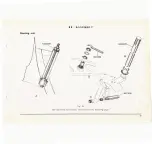
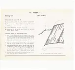
Page 64: ...d part of the pressing as indicated in fig 38 by the letter a b Place the new steering column cover over the welded flanges of the old one clamp in posi tion and using the existing holes in the new pa...

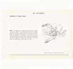
Page 65: ...and 12723 1 for mods AC 2 and AC 3 WORKCYCLE A Retouches of major entity where the metal is exposed rusted or the paint work is not sufficiently adherent 1 Rub down the zone in question so as to com p...

Page 66: ...ndard tools are not included Before car rying out any of the operations it is advisable first consult the spare parts list which illustrates each group subdivided into its component parts N B Before a...

Page 67: ...1812 A T 0021071 O Fig 39 A Ball bearing on crankcase half clutch side and oil seal Heat seal housing and position seal so that the flange cut out coincides with the corresponding hole on crankcase B...

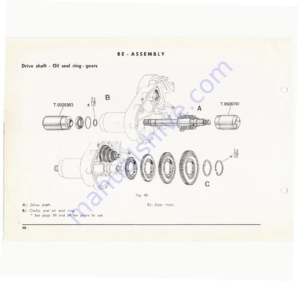
Page 68: ...RE ASSEMBLY Drive shaft Oil seal ring gears I B A T 0020781 0 M c Fig 40 I A Drive shaft B Circlip and oil seal ring See pags 19 and 24 for pliers to use C Gear train 68...

Page 69: ...RE ASSEMBLY Crankcase flywheel side Starter unit a T OO201 i A B Fig 41 A Heat crankcase B Components of starter unit 69...

Page 70: ...RE ASSEMBLY Crankshaft Mating crankcase halves A Fig 42 See notes on following page 70...

Page 71: ...r this inspection C Crankshaft into crankcase half clutch side it is ad visable carry out this operation immediately after having mounted the oil seal ring insomuch as the bearing seating is still war...

Page 72: ...then decends to the point where the incision on the cursor of the indexing tool is in line with that on the sleeve again read off the new value on the graduated disc with respect to the fixed index t...

Page 73: ...ss caps with the convex face outwards L A Fig 44 T 002 436 8 The flat plain on the planetary shaft indicated in the detail A should be assembled facing away from the dowel hole as indicated in the fig...

Page 74: ...and circlips N B Intr duce the splined shaft shank sun Yllheel of the differe tial D Internal bearing of bracket wheel hub E Outer bearing circlip F Oil seal and threaded lock ring of internal bearing...

Page 75: ...Steering unit A RE ASS EMB l Y I 4 D See operations list and assy instructions on the following page Fig 46 75...

Page 76: ...well greased 28 ball bearings approx 0 4 mm for upper bearing 2Jnd19 ball beurings of approx 0 8 mm for lower steering column bearing 2 After having introduced the steering column into the frame chec...

Page 77: ...ther specific parts as indicated on spare parts list Connect the control cables as indicated in the diagram If the vehicle is to be furnished with both electrical starter motor and mechanical hand lev...

Page 78: ...with the corresponding component of the starter group Apply pressure to the detail c so as to introduce it into the tube position the group as indicated in fig so that on releasing the pin c it enter...

Page 79: ...nts to substitute and for the di sposition of the various parts on assembling the tip up platform consult the spare parts list A 4 85 For mounting the tip up platform to vehicle chassis pro ceed as fo...

Page 80: ...n the vehicle Check that under no conditions the shock absorbers remain locked 4 Check for absence of oil and fuel loses 5 Ch k t 3 25 3 4 Kgjcmq f ec yre pressures j 47 7 50 or rear tyres r p s 1 d 1...

Page 81: ...JJ STABILIMENTO DI PONTEDERA UFFICIO TECNICO SERlE DIS N 88884 1sT EDITION 1000 6201 TIP MORI _J...

Reviews: