4
4 - 5
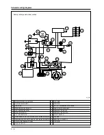
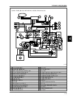
Electrical equipment diagram
Electrical equipment devices
1
. Digital instrument panel (11 LED indicators).
2
. Analog instrument panel (5 bulbs).
3
. Headlight (2 parking light bulbs, 55/55W low/high
beam bulbs).
4
. LH front turn indicators (10W bulb).
5
. Rear brake light button.
6
. Lights selector switch with headlight flash.
7
. Turn indicator switch.
8
. Horn button.
9
. Hazard warning light button.
10
. Reset button.
11
. Trumpet horn.
12
. Sidestand switch.
13
. Voltage regulator.
14
. Stand control unit.
15
. Engine stop relay switch.
16
. Electronic control unit relay switch.
17
. Stand pump relay switches.
18
. LH rear light (5W parking light bulb, 10W turn
indicator bulb).
19
. Rear brake light (5 x 2.3W bulbs).
20
. Number-plate light with bulb.
21
. RH rear light (5W parking light bulb, 10W turn
indicator bulb).
22
. 12V-14Ah battery.
23
. Fuse box (3 x 7.5A fuse, 1 x 15A fuse).
24
. Starting relay switch.
25
. Flywheel magneto (375W).
26
. Engine oil pressure sensor.
27
. Coolant temperature sensor.
28
. Engine rpm sensor.
29
. Air temperature sensor.
30
. Idle speed adjusting motor.
31
. Throttle potentiometer.
32
. Petrol injector.
33
. 2 stand switches.
34
. Stand pump motor.
35
. Injection electronic control unit.
36
. Decoder.
37
. Front brake light button.
38
. Engine stop switch.
39
. Wheel revolution sensor.
40
. RH front turn indicator (10W bulb).
- When working on the electrical equip-
ment, take special care to ensure that the leads that link
up to the electronic control device are properly con-
nected by observing the polarity and colour coding of
the connectors.
ELECTRICAL CABLES COLOUR:
B
=White -
Bl
=Blue
-
G
=Yellow -
Mr
=Brown -
N
=Black -
BV
=White-Green -
GN
=Yellow-Black -
Gr
=Grey -
Rs
=Pink -
R
=Red -
Vi
=Violet -
V
=Green -
VN
=Green-Black -
BN
=White-
Black -
BBl
=White-Blue -
GV
=Yellow-Green -
Ar
=Orange -
Az
=Azure -
GrBl
=Grey-Blue -
GrN
=Grey-
Black.
Warning
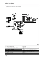
41
. Relay switch.
42
. Lights switch.
43
. Start button.
44
. Stand button.
45
. Immobilizer aerial.
46
. Ignition switch.
47
. Electric fan.
48
. Electric fan relay switch.
49
. Main relay switch.
50
. HV coil.
51
. Fuel gauge with pump.
52
. Starter motor.
53
. Helmet compartment lamp button.
54
. Helmet compartment lamp.
55
. 12V socket.
56
. 2 rear fuse boxes for control unit (1 x 3A fuse, 1 x 5A
fuse, 1 x 10A fuse, 1 x 3A fuse).
57
. Radio display.
58
. Relay switch.
59
. Outside temperature sensor.
60
. Diode box (2 x 6A/2A diodes).
61
. Fuse box (2 x 7.5A fuse, 1 x 15A fuse, 1 x 5A fuse).
62
. Fuse box with base for stand pump (1 x 70A fuse).
63.
Intercom/radio control unit.
64.
Intercom connectors.
65.
Relay signaler glued.
Summary of Contents for X9 500 cc
Page 7: ...TABLE OF CONTENTS SPECIFIC TOOLING 2...
Page 17: ...TABLE OF CONTENTS ELECTRICAL EQUIPMENT 4...
Page 34: ...TABLE OF CONTENTS ENGINE 5...
Page 43: ...TABLE OF CONTENTS BRAKING SYSTEM 7...
Page 51: ...TABLE OF CONTENTS BODYWORK 8...


