background image

4 - 14

The reserve fuel, turn indicator and hazard warning lights are activated by the electronics of the instrument. For
example, the fuel reserve warning light comes on only when the reserve fuel indication from the fuel tank lasts a
minimum of 13.5 seconds. This prevents the warning light from blinking when the engine begins to run on reserve
fuel.

- The flashing function is built in the electronics of the instrument, which allows the hazard warning lights to work

when the ignition switch is in the “OFF” position and the control switch is disabled. The control switch is active only
when the instrument panel is on.

For greater riding safety, the “turn indicator control” function is connected to the mileometer. If the turn indicators are
inadvertently left on, they are automatically switched off after 1 kilometre.

- The “engine start disabled” warning light is activated by the sidestand switch and the emergency switch on the right

side of the handlebar.

- The indication “brake light bulb burnt-out” is activated when at least two of the five bulbs fail to operate.
- The warning light is controlled by a circuit that measures the absorption of the brake light bulb.
- The liquid crystal display shows a 5-digit total mileage count in either kilometres or miles. Naturally, this counter

can never be reset. 

To select the unit, with key turned to “OFF”, press the “Trip” and “M” buttons at the same

time and turn the ignition switch to the “ON” position. If the two buttons are depressed for longer than three
seconds, the word “SET” is displayed and then the unit toggles between kilometres and miles.

Electrical equipment

Instrument panel

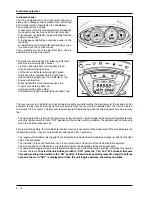
The X9 is equipped with a dual instrument panel con-
sisting  of an analog section installed in the front fairing
and a digital section mounted on the handlebars.
The analog section includes:
- A dual-scale (km/h-mph) speedometer controlled by

the speed sensor by means of the digital section;

- A tachometer controlled by a signal coming from the

power unit-injection;

- A fuel gauge controlled by a resistive sensor (in the

fuel tank);

- A coolant temperature indicator controlled by a resis-

tive sensor (on the cylinder head).

These instruments are of the electrical type, and are
operated by step-by-step motors.

The digital section includes the following indicators:
- Reserve fuel warning light: amber.
- Lights-on and low beam warning light: green.
- High beam warning light: blue.
- Left-hand turn indicator warning light: green.
- Right-hand turn indicator warning light: green.
- Hazard warning lights (four turn indicators): red
- Engine disabled: red.
- Brake light bulb burnt-out warning light: red.
- Oil pressure warning light: red;
- Injection warning light: amber;
- ALARM warning light (electrohydraulic cable): red.

04_009

04_010

Summary of Contents for X9 500 cc

Page 1: ...D Pontedera PI Copyright 2001 PIAGGIO C S p A Pontedera All rights reserved Reproduction in whole or in part forbidden Data subject to change without notice No responsibility is assumed for the use of...

Page 2: ...this manual Since satisfactory results cannot be obtained without the necessary equipment and tooling we recommend referring to the pages of this manual concerning the specific equipment required and...

Page 3: ...PECIFICATIONS AND OVERHAUL DATA SPECIFIC TOOLING MAINTENANCE AND TROUBLESHOOTING ELECTRICAL EQUIPMENT FRONT AND REAR SUSPENSIONS BRAKING SYSTEM BODYWORK PREDELIVERY OPERATIONS TABLE OF WORKING TIMES E...

Page 4: ...S CLEARANCE SEAT CLEARANCE CODE CLEARANCE AFTER USE 1st Compression ring 92 x 1 5 A 0 15 0 35 0 5 2nd Compression ring 92 x 1 25 A 0 25 0 50 0 65 Scraper ring 92 x 2 5 A 0 25 0 50 0 65 Values in mm Th...

Page 5: ...jection or recess value it indicates the type of gasket to be fitted on the cylinder to restore the compression ratio Therefore the more the surface formed by the piston crown sticks out of the surfac...

Page 6: ...0 10 mm Standard diameter Class 1 40 010 40 016 Class 2 40 016 40 022 PART DIMENSIONS CLEARANCE Web transmission side A 0 8 0 025 Shaft section transmission side B 19 6 0 05 Connecting rod C 22 0 10 S...

Page 7: ...TABLE OF CONTENTS SPECIFIC TOOLING 2...

Page 8: ...Support for METABO HG 1500 2 air heater 020150Y METABO HG 1500 2 air heater 020151Y Mityvac type vacuum pump 020329Y Stroboscopic gun for two and four stroke engines 020330Y Digital multimeter 020331Y...

Page 9: ...l pressure gauge unio 020434Y 17 mm guide countershaft bearings 020439Y Driven half pulley spring compressor 020444Y 46 55 mm spanner 020444Y009 24 mm adaptor 020456Y Steering tube lower bearing extra...

Page 10: ...lug of the recommended type Insert the plug into the hole with the proper inclina tion screw it in fully by hand and then tighten it with the specially designed spanner Tightening torque 10 N m 1 Kg m...

Page 11: ...the MAX level Approximately 400 cc of oil are needed to restore the level between the MIN and MAX marks Oil pressure warning light A warning light on the instrument panel comes on when the ignition k...

Page 12: ...gasket makes contact and then tighten it with the prescribed torque Reinstall the silencer Add engine oil as previously described Tightening torque Tappo scarico olio motore Engine oil drain plug 24 3...

Page 13: ...ntheexpansion tank The level of the fluid should always be between the MIN and MAX marks To have an indication of the coolant level refer to the groove in the plastic strip that can be seen through th...

Page 14: ...Checkingthevalve gear timing To adjust the play of the valves and to check the valve gear timing as described in Chapter 7 Thermal Unit and Timing system of the Engine manual follow these preliminary...

Page 15: ...er draw the fluid from open or partly empty contain ers Under normal climatic conditions the fluid should be renewed every 20 000 km or in any case every two years N B Change the brake fluid and bleed...

Page 16: ...wn on the screen To shift the head light use the specially designed screw in the front shield see figure 03_018 03_016 03_017 Push the bolt lightly and extract the retainer from the milled part shown...

Page 17: ...TABLE OF CONTENTS ELECTRICAL EQUIPMENT 4...

Page 18: ...ELECTRICAL EQUIPMENT 1 2 3 4 5 6 7 8 9 10 11 12 13 14 15 16 17 18 19 20 21 22 23 24 25 26 27 28 29 30 31 32 33 34 35 36 37 38 39 40 41 42 43 44 45 46 47 48 49 50 51 52 TURN INDICATOR SWITCH HORN BUTT...

Page 19: ...r 35 Injection electronic control unit 36 Decoder 37 Front brake light button 38 Engine stop switch 39 Wheel revolution sensor 40 RH front turn indicator 10W bulb When working on the electrical equip...

Page 20: ...SPARK PLUG DIGITAL INSTRUMENT SET 5A FUSE 3A FUSE 04_002 IMMOBILIZER AERIAL ENGINE STOP RELAY SWITCH MAIN RELAY SWITCH 12V 14Ah BATTERY 30A FUSE ENGINE STOP SWITCH 10A FUSE ELECTRONIC POWER UNIT ELECT...

Page 21: ...GHT BULB IGNITION SWITCH CONTACTS MAIN RELAY SWITCH FLYWHEEL MAGNETO VOLTAGE REGULATOR 7 5 A FUSE 15 A FUSE 7 5 A FUSE 7 5 A FUSE 30 A FUSE 12V 14Ah BATTERY HELMET COMPARTMENT LAMP BUTTON 12V 5W HELME...

Page 22: ...FRONT BRAKE LIGHT BUTTON AND START INHIBITOR SWITCH REAR BRAKE LIGHT BUTTON AND START INHIBITOR SWITCH DIGITAL INSTRUMENT PANEL START BUTTON 30A FUSE 6A DIODE 5 X 12V 2 3W BRAKE LIGHT BULB INJECTION P...

Page 23: ...MOTOR ENGINE TEMPERATURE SENSOR FLYWHEEL MAGNETO VOLTAGE REGULATOR 16 17 18 19 20 21 22 23 24 25 26 27 28 29 30 30A FUSE 12V 14Ah BATTERY 70A FUSE STAND HYDRAULIC PUMP RELAY SWITCHES STAND HYDRAULIC P...

Page 24: ...NT PANEL TURN INDICATORS 2 2 X 12V 10W BULB TURN INDICATOR SWITCH ACCESSORIES PREWIRING HORN BUTTON HORN 15A FUSE GNITION SWITCH CONTACT 7 5A FUSE 7 5A FUSE MAIN RELAY SWITCH PRESETTING FOR INTERCOM P...

Page 25: ...ENGINE START DISABLED WARNING LIGHT INPUT OIL PRESSURE WARNING LIGHT INPUT 19 20 21 22 23 24 25 26 27 28 29 30 31 32 33 34 35 36 MALFUNCTIONING BRAKE LIGHT WARNING LIGHT INPUT LH TURN INDICATOR OUTPUT...

Page 26: ...voltage ensure that no electrolyte is leaking from the battery 2 Turn the ignition key to the OFF position and connect the tester terminals between the battery negative pole and the black cable 3 Deta...

Page 27: ...placethestator Checking the peak current With the engine off and swithboard ON turn the vehicle lights on and let the battery tension set to 12V Connect the amperometric pliers to the 2 outlet re char...

Page 28: ...ometres or miles Naturally this counter canneverbereset Toselecttheunit withkeyturnedto OFF pressthe Trip and M buttonsatthesame timeandturntheignitionswitchtothe ON position Ifthetwobuttonsaredepress...

Page 29: ...10W x 2 Rear parking light bulb spherical 12V 5W x 2 Brake light bulbs spherical 12V 2 3W x 5 Rear turn indicator bulb spherical 12V 10W x 2 Instrument panel lighting bulb all glass 12V 2W x 5 Glove...

Page 30: ...ific weight 1 26 corresponding to 30 B at a temperature of at least 15 C 2 Leaveatrestforatleasttwohoursandthenrestore the level by adding sulphuric acid 3 Recharge within 24 hours by means of the spe...

Page 31: ...ement At last fit the left side element NOTCHING NOTCHING Cut the breather pipe supplied as shown in the figure 04_022 Fit the pipe until it contacts the battery and in the direction shown in the figu...

Page 32: ...pipe with a tear clamp and cut the end that sticks out of the clamp Insert the battery in the compartment taking care to fit the breather pipe in the bottom hole Insert the battery in the compartment...

Page 33: ...with Vaseline Never use fuses having a greater ca pacity than the one recommended The use of a fuse of unsuitable capacity may result in serious damage to the whole vehicle or even cause a fire Warni...

Page 34: ...TABLE OF CONTENTS ENGINE 5...

Page 35: ...ol Disconnect the air filter sleeve and the engine oil values collecting pipe Disconnect the earth cable from the engine Disconnect the electrical devices from the throttle body head and starter feed...

Page 36: ...ve the nut shown in the figure Remove the pin Now the engine is free Engine assembly to vehicle Perform the assembly in the reverse order observing the tightening torques indicated in Chapter 1 Take c...

Page 37: ...d on it Take care not to damage the flexible trans missions the pipes or the bodywork Fitting Perform the removing procedure in reverse order To align the handlebar with the steering tube align the no...

Page 38: ...bearing by following the same procedure as the other bearings 06_006 Refit the two front brake discs as described in Chap ter 7 Braking system Fit the outer spacer and the related ring taking care no...

Page 39: ...both rings support the fork assembly so as to prevent it from falling Pull out the fork assembly Specific tool Steering tube ring spanner 020055Y Caution Warning Front and rear suspensions Replacing t...

Page 40: ..._014 Front and rear suspensions Lubricate the steering bearing housing with grease of the TUTELA Z2 type Fit the steering tube into the sleeve Fit the spacer Fit the lower ring tighten it with the pre...

Page 41: ...rbers Removal Follow these steps Put the vehicle on the central stand Using a jack slightly lift the engine so as to free both shock absorbers Remove the silencer Unloose the shock absorber spring ass...

Page 42: ...the bracket as described in Chapter 5 Engine Remove the 5 screws fixing the rear wheel to the hub Take down the wheel Fitting Fit the wheel using the reverse procedure to the re moval Tighten the rea...

Page 43: ...TABLE OF CONTENTS BRAKING SYSTEM 7...

Page 44: ...H OIL APPLY PRODUCT LUBRICATE WITH GREASE CLEAN CAREFULLY ALWAYS REPLACE WARNING HANDLE WITH CARE CALLOUT A B C D E F G H I L M N O QUANTITY 6 4 3 1 1 1 2 2 10 5 TORQUE N m 20 25 42 62 15 20 20 25 20...

Page 45: ...per from its support Remove the retaining ring and the pin Remove the two pads by pulling them downwards Check the thickness of the pads Wear limit 1 5 mm If the thickness of the pads is less than the...

Page 46: ...seat on the hub Replacing the front brake discs Follow these steps Remove the front wheel as described in Chapter 6 Front and rear suspensions For each disc loosen the five screws shown Carefully clea...

Page 47: ...eft immersed in alcohol for longer than 20 seconds After the washing dry the parts with a compressed air jet and wipe them with a clean cloth Seal rings must be immersed in the liquid of use The use o...

Page 48: ...ven for the right hand front brake using the bleeder of both brake calipers front and rear To bleed the system follow these steps 1 Attach the specific Mityvac tool to the bleeder fitted on the pressu...

Page 49: ...n by filling and bleeding the circuit Use the same procedure for the three calipers the only difference being that the rear brake caliper must be removed from the vehicle together with its support Thi...

Page 50: ...8 Bodywork Unscrew rear caliper connection 1 see figure Note Place a rag under the divider valve to prevent brake fluid from soiling the brake pads or other compo nents Remove front brake caliper conn...

Page 51: ...TABLE OF CONTENTS BODYWORK 8...

Page 52: ...PRODUCT LUBRICATE WITH GREASE CLEAN CAREFULLY ALWAYS REPLACE WARNING HANDLE WITH CARE Perform all operations with great care Plastics are easily damaged Avoid cleaning painted plastics with solvents...

Page 53: ...e to properly reinsert the weather strips into their seats Front central cover Lift the rearview mirror covers Unscrew the five fixing screws shown in the figure Remove the front central cover with th...

Page 54: ...side Digital instrument panel support Remove the three fixing screws Detach the electrical connectors Remove the support with the digital instrument panel Pay special attention to the electrical conne...

Page 55: ...TABLE OF CONTENTS TABLE OF WORKING TIMES 10...

Page 56: ...ption Time 1 001133 Crankcase Replacement 410 2 001153 Crankcase half gasket Replacement 280 3 001100 Oil seal clutch side Replacement 60 1 ENGINE Op Code Description Time 1 001001 Engine from frame R...

Page 57: ...cement 70 2 001093 Spark plug Replacement 15 3 001088 Cylinder head cover gasket Replacement 70 8 FLYWHEEL COVER Op Code Description Time 1 001087 Flywheel cover Replacement 105 2 001113 Water pump Re...

Page 58: ...42 Oil pump Overhaul 280 3 001051 Timing chain belt Replacement 220 4 001125 Chain guide shoes Replacement 225 11 REDUCTION GEARING ASSEMBLY Op Code Description Time 1 001010 Reduction gearing Overhau...

Page 59: ...er pinion Replacement 90 3 003064 Engine oil Replacement 20 1 2 3 1 2 16 THROTTLE BODY Op Code Description Time 1 001013 Intake manifold Replacement 75 2 001047 Injector Replacement 70 3 001166 Thrott...

Page 60: ...ust manifold Replacement 20 3 001095 Silencer guard Replacement 5 4 001136 Exhaust emissions Adjustment 30 1 2 1 4 2 3 19 TANK Op Code Description Time 1 004073 Fuel pump Replacement 20 2 004005 Fuel...

Page 61: ...d Replacement 65 1 2 1 24 FRONT SHIELD Op Code Description Time 1 004064 Front shield front section Replacement 35 2 006012 Front shield Painting 30 3 004149 Front shield central cover Replacement 10...

Page 62: ...pening cable Replacement 50 4 004156 Glove compartment door and or support Replacement 40 1 2 2 1 2 4 4 3 28 EXPANSION TANK Op Code Description Time 1 007001 Expansion tank Replacement 40 2 007013 Exp...

Page 63: ...itting 45 6 002083 Saddle opening cable Replacement 70 1 3 4 2 3 4 2 5 6 1 32 FRONT MUDGUARDS Op Code Description Time 1 004002 Front mudguard Replacement 10 2 006003 Front mudguard Painting 30 31 MAT...

Page 64: ...S Op Code Description Time 1 004119 Steering upper thrust ring bearing Replace 60 2 003002 Steering thrust rings Replacement 80 3 003073 Steering play Adjustment 30 1 2 3 5 2 4 1 3 36 REAR SHOCK ABSOR...

Page 65: ...pump tube device Replacement 60 3 002085 Front caliper all wheel braking device tube Replacement 60 4 002087 All wheel braking rear rigid tube Replacement 80 5 002090 All wheel brake fluid Renewal an...

Page 66: ...lb Replacement 10 5 005012 Front turn indicators Replacement 30 6 005091 Turn indicators glass Replacement 5 3 4 1 2 5 6 3 2 5 4 6 1 2 5 4 6 44 REAR COVERS Op Code Description Time 1 004057 Tail lamp...

Page 67: ...attery Replacement 20 3 005011 Starting relay switch Replacement 20 4 005097 Electrical central stand electromagnetic switch Replacement 20 5 001094 Spark plug cap Replacement 15 6 005024 Battery fuse...

Page 68: ...fuse holder Replacement 10 3 2 1 3 2 1 52 FRONT WHEEL Op Code Description Time 1 003037 Front wheel rim Removal and refitting 30 2 003047 Front tyre Replacement 20 3 004123 Front wheel Replacement 20...

Page 69: ...eplacement 45 3 001016 Rear wheel Replacement 35 4 006018 Wheel rim Painting 35 5 003063 Tyre pressure Check 5 6 003014 Rear suspension arm Replacement 20 7 003077 Silencer rear shock absorber support...

Reviews: