6 - 3
6
Front and rear suspensions
Handlebar
Removal
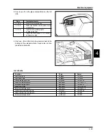
- Begin by removing the radio-interphone and then
disconnect the feeder cable.
- Remove the digital panel support and the front and
rear sections of the handlebar cover as described in
Chapter 8-Bodywork.
- Disengage the handlebar from the components in-
stalled on it.
- Remove the two counterpoises after loosening the
side screws.
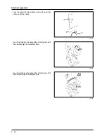
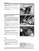
- Remove the pumps after loosening the screws on the
clevises shown in the figure.
- Slide the throttle control off the handlebar after loos-
ening the fixing screws.
- Remove the left handgrip.
- Loosen the bolt fastening the handlebar to the steer-
ing tube shown in the figure and then remove it.
Remove the handlebar and the plastic support.
Note
: If the handlebar is removed to proceed to the
removal of the front fork, simply overturn the handlebar
onto the front of the vehicle without removing the parts
fitted on it. Take care not to damage the flexible trans-
missions, the pipes or the bodywork.
Fitting
Perform the removing procedure in reverse order. To
align the handlebar with the steering tube, align the
notch on the handlebar with the notch on the sterring
tube. Tighten the fasteners with the torques specified in
Chapter 1.
Tightening torques:
Handlebar fastening bolt: 43 - 47 N·m
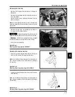
Removing the front wheel
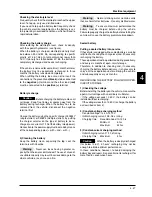
- Remove the two brake calipers as described in
Chapter 7-Braking system.
- Unscrew the axle locknut.
- Disengage the axle by loosening the two screws on
the right-hand fork sheath (see figure).
- While supporting the wheel, remove the axle on the
right side of the vehicle.
- When removing the wheel, take care
not to damage the speed sensor.
06_004
06_003
06_002
06_001
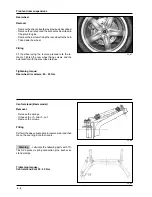
Overhauling the front wheel
Check the bearings for any excessive play or stickiness
causing noise and uneven rotation of the wheel.
Should the wheel bearings need to be replaced, follow
these steps:
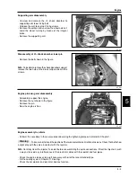
- Using a suitable extractor on the inner race, remove
the two bearings on the left side of the wheel (speed
sensor side).
Caution
Summary of Contents for X9 500 cc
Page 7: ...TABLE OF CONTENTS SPECIFIC TOOLING 2...
Page 17: ...TABLE OF CONTENTS ELECTRICAL EQUIPMENT 4...
Page 34: ...TABLE OF CONTENTS ENGINE 5...
Page 43: ...TABLE OF CONTENTS BRAKING SYSTEM 7...
Page 51: ...TABLE OF CONTENTS BODYWORK 8...

