PianoDisc Installation Guide
31
. . . . .
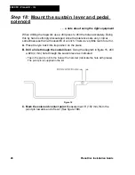
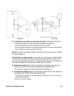
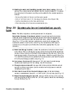
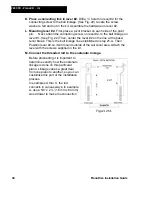
G. Marking location and installing sustain lever return spring.
On most
pianos, the sustain pedal feels lighter that the original trapwork. To replace
the same feel to the pedal, a spring can be added to the sustain pedal as
follows:
•
Remove the bottom of the lyre and the sustain pedal.
•
Drill a 1” (25 mm) hole ½” (13 mm) deep into the lyre. (See Figure 16B)
•
Felt the circumference to the hole with thin felt.
•
Place the spring in the hole and reassemble the lyre.
Step 20:
Sostenuto lever installation push
type
Note
: PianoDisc requires a working sostenuto on all pianos.
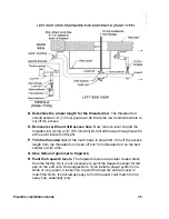
Determine the type of sostenuto action.
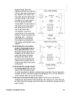
In grand pianos there are two
methods used to operate the sostenuto pedal. One method engages the
sostenuto by pushing up under the sostenuto lever, called a “push” action.
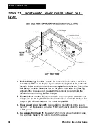
(See Fig. 17) The other method, pulls down a lever which engages the
sostenuto, called a “pull” action. (See Fig. 20). Determine which type of
sostenuto is on the piano and follow the instruction appropriate for your
situation.
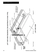
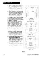
A. Mark ball linkage location.
Locate the sostenuto connection at the bass/
tenor break. Place a 90 degree square across the keybed at the sostenuto
location. Draw a line from the back of the keybed across the slot. This is the
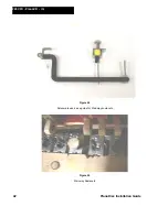
ball linkage location. Place the lyre on the piano. Hold the lever #1 (See Fig.
17) under the sostenuto rod, parallel to the solenoid slot, and mark the lever
#1 for the ball linkage location. (See Fig. 17)
B. Cut excess from lever #1.
Measure 2” (51 mm) past the ball linkage
location and mark lever #1 for cutting. Cut off the excess.
C. Place pivot pins in lever #1.
Using a # 20 (4 mm) drill bit, drill both ends of
lever #1 and tap in pivot pins. (Use a small amount of grease to aid with
installing the pivot pins.)
D. Drill hole in lever #1 for the ball linkage screw.
At the ball linkage
location, established in step 20 – A, Drill a 3/16” (5 mm) hole. (See Fig. 17)
E. Mount the ball linkage to lever #1.
Using a 10/32 (4 mm) x 3/4” (19 mm)
pan head slotted screw and the 3/4” (19 mm) spacer, attach the ball linkage
to lever #1(See Fig. 17)
Summary of Contents for PianoCD
Page 1: ...PIANODISC SYSTEMS Installation Guide for Grand Pianos Version R C 6 8 07...
Page 7: ...PianoDisc Installation Guide 7...
Page 18: ...18 PianoDisc Installation Guide 228CFX PianoCD iQ Figure 7A...
Page 19: ...PianoDisc Installation Guide 19 Figure 7B...
Page 32: ...32 PianoDisc Installation Guide 228CFX PianoCD iQ...
Page 52: ...52 PianoDisc Installation Guide 228CFX PianoCD iQ Figure 35...
Page 62: ...62 PianoDisc Installation Guide 228CFX PianoCD iQ...
Page 64: ...64 PianoDisc Installation Guide 228CFX PianoCD iQ...
Page 68: ...68 PianoDisc Installation Guide 228CFX PianoCD iQ...
Page 84: ...84 PianoDisc Installation Guide 228CFX PianoCD iQ...

