PianoDisc Installation Guide
49
. . . . .
B.
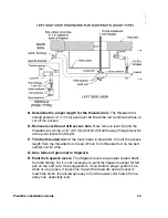
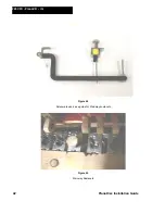
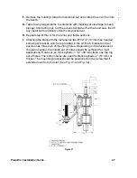
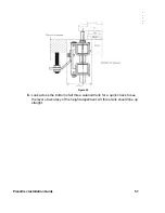
Place end keys of each section or group on the key frame. Put the key
frame in the piano and put the cheek blocks in place. To determine where to
drill the holes in the keybed for the hanger bolts, place the stud locator on
the solenoid rail brackets. Hold the completed section of a rail in the slot
and align plunger tips with the end keys. Now tap the pins on the stud
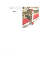
locator blocks to index stud location. (See Figure 33) Repeat this procedure
for the other two rails.
Alternate method for determining placement of rail mounting stud:
With the key frame in the piano, hold a completed section of the rail in the
slot. Align plunger tips with the end keys. Note the position of the mounting
stud. With a pencil, outline that hole on the keybed.
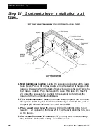
C.
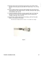
A 1/4" (6 mm) hole must be pre-drilled approximately 1" (25 mm) deep for
the hanger bolt, and it must be drilled straight. This can be accomplished by
using either a guide block or a drill guide. To insert the hanger bolt, use a
"stud installer" supplied by PianoDisc at the training class, or put both jam
nuts on the stud, tighten them against one another and screw the stud into
the keybed. With the hanger bolts in position, remove one of the jam nuts
from each stud. Place the solenoid rail on the two studs, adjusting the nuts
so that the rubber tips of the plungers barely touch the bottom of the keys.
Replace the remaining jam nuts to hold the rail in place. Check to see if the
plunger tip is centered on the keys, adjust if necessary.
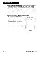
NOTE:
This is the temporary position of the solenoid rail. Action regulation
must be done before the final height adjustment of the solenoid rails.
Step 26
: Mounting & connecting key driver
boards
NOTE
: The 3 key driver boards are identical. The 2 key driver boards that
have a “L” shaped mounting bracket, must be place at the bass and tenor
sections. The flat mounting bracket is always placed at the treble section.
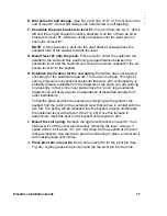
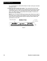
A. Connecting solenoids to key driver boards
. Since there are a total of 90
key solenoid connections on the three driver boards, two positions will not
be used on the 88 note keyboard. Attach the connector of solenoid #1 to the
first key solenoid header pins (near the pedal connector) on the bass driver
board. Continue moving to the right until all 88 connections have been
completed. This means, that the last two sets of output pins on the treble
board (at the right-most end) will remain empty.
NOTE:
In the event that space limitations, where not all 88 solenoids were
used within the piano, it will be necessary to omit the first two or three
connections. Every two pins on the key driver board are used for one key
solenoid connection.
Summary of Contents for PianoCD
Page 1: ...PIANODISC SYSTEMS Installation Guide for Grand Pianos Version R C 6 8 07...
Page 7: ...PianoDisc Installation Guide 7...
Page 18: ...18 PianoDisc Installation Guide 228CFX PianoCD iQ Figure 7A...
Page 19: ...PianoDisc Installation Guide 19 Figure 7B...
Page 32: ...32 PianoDisc Installation Guide 228CFX PianoCD iQ...
Page 52: ...52 PianoDisc Installation Guide 228CFX PianoCD iQ Figure 35...
Page 62: ...62 PianoDisc Installation Guide 228CFX PianoCD iQ...
Page 64: ...64 PianoDisc Installation Guide 228CFX PianoCD iQ...
Page 68: ...68 PianoDisc Installation Guide 228CFX PianoCD iQ...
Page 84: ...84 PianoDisc Installation Guide 228CFX PianoCD iQ...

