background image

Il 

lib

re

tto

 is

tru

zio

ni

 é

 p

ar

te

 in

te

gr

an

te

 d

el

 p

ro

do

tto

. -

 T

he

 in

st

ru

ct

io

bo

ok

le

t i

an

 in

te

gr

al

 p

ar

t o

f t

he

 p

ro

du

ct

Italiano

English

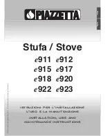
istruzioni per l’installazione

l’uso e la manutenzione

installation, use and

maintenance instructions

Stufa / Stove

e

911

e

912

e

915  

e

917

e

918  

e

920

e

922  

e

923

Summary of Contents for covering e920

Page 1: ... del prodotto The instruction booklet is an integral part of the product Italiano English istruzioni per l installazione l uso e la manutenzione installation use and maintenance instructions Stufa Stove e911 e912 e915 e917 e918 e920 e922 e923 ...

Page 2: ...sabilità per danni causati dalla inosservanza alle norme di installazione uso e manutenzioni indicate nel libretto di istruzioni per modifiche del prodotto non autorizzate o ricambi non originali L installazione e l utilizzo del prodotto deve essere fatta in conformità con le istruzioni del fabbricante e nel rispetto delle normative europee nazionali e dei regolamenti locali Prima di installare il...

Page 3: ...omburente 21 DT2010462 00 3 3 Prima accensione 21 DT2010045 01 3 4 Accensione 22 DT2010044 02 3 5 Apertura della porta 22 DT2010046 00 3 6 Funzionamento notturno al minimo 23 DT2010047 00 3 7 Funzionamento in condizioni atmosferiche avverse 23 DT2010048 00 3 8 Surriscaldamento e spegnimento 23 DT2010051 00 3 9 Umidificatore 23 DT2010464 00 3 10 Uso del forno 23 DT2010395 00 4 0 Manutenzione 24 DT2...

Page 4: ... CANNA FUMARIA COLLEGAMENTO ALLA CANNA FUMARIA ISPEZIONE PER RACCOLTA FULIGGINE PRESA D ARIA ESTERNA VERIFICA PORTATA SOLAIO DISTANZE DI SICUREZZA ISPEZIONE Controllare che tutte le voci qui sotto elencate siano conformi all installazione con il vostro prodotto Fig 1 ...

Page 5: ...ndati con raggio non inferiore a 20mm avente un rapporto massimo tra i lati di 1 5 fig 3 4 5 le pareti devono essere il più possibili lisce e senza restringimenti le curve regolari e senza discontinuità fig 6 È proibito praticare aperture fisse o mobili sulla canna fumaria per collegare apparecchi diversi da quello a cui è asservita È vietato far transitare all interno della canna fumaria sebbene ...

Page 6: ...comignolo deve essere posizionato in modo da garantire un adeguata dispersione e diluizione dei prodotti della combustione e comunque al di fuori della zona di reflusso Tale zona ha dimensioni e forme diverse in funzione dell angolo di inclinazione della copertura per cui risulta necessario adottare le altezze minime riportate in fig 10 11 Esempio Verificare l inclinazione del tetto colonna α e la...

Page 7: ... non essere ostruita L aria necessaria per il focolare si può ottenere nei differenti modi tramite una griglia esterna diretta all ambiente di installazione fig 12 con una canalizzazione tramite dei tubi diretti all ambiente di installazione maggiorando la sezione minima libera indicata di almeno il 15 fig 13 attraverso un foro comunicante da un locale adiacente al luogo di installazione solo se t...

Page 8: ...ne anche se installati in ambienti attigui e comunicanti con il locale di installazione 1 6 Portata del solaio Verificare la capacità portante del solaio facendo riferimento al peso del prodotto nel paragrafo Dati tecnici Se il solaio non ha una idonea capacità portante si devono prendere adeguate contromisure ad esempio utilizzando una piastra in lamiera per distribuire il carico 1 7 Capacità di ...

Page 9: ... orizzontale non superiore a 2 m Figure 17 18 19 I raccordi devono essere il più brevi possibili privi di strozzature realizzati in materiali resistenti alla corrosione dei fumi e a temperature di 550 600 C Per il collegamento alla canna fumaria si consiglia di usare tubi e curve del Gruppo Piazzetta S p A in quanto lo scarico fumi del prodotto è dimensionato per l innesto di questi inoltre le cur...

Page 10: ...mabili le intercapedini devono essere riempite con materiali non infiammabili indeformabili e con ridotta capacità di trasmissione del calore per esempio calcestruzzo leggero Figura 23 oppure le intercapedini possono essere protette con appositi tubi di protezione Figura 22 Controllare che il collegamento alla canna fumaria sia effettuato in modo da garantire la tenuta ai fumi per le condizioni di...

Page 11: ...pio H 80 cm 80 24 5 5 60 5 H Raccordo C6 Innesto tubo Lunghezza tubo Un tubo da 100 cm T100 va tagliato a 60 5 cm Il tubo va tagliato dalla parte del maschio Calcolo indicativo del tratto di tubi orizzontale conoscendo E Esempio su stufa e917 E 50 cm D 38 cm 50 38 24 5 5 68 5 E D Raccordo C6 Innesto tubo Lunghezza tubo Un tubo da 100 cm T100 va tagliato a 68 5 cm Il tubo va tagliato dalla parte de...

Page 12: ...ere al di fuori della zona di irraggiamento del focolare e comunque alla distanza di almeno 1m dal blocco riscaldante tutti gli elementi di materiale combustibile o infiammabile Per altre nozioni fare riferimento al paragrafo Distanze di sicurezza e Collegamento alla canna fumaria Il condotto scarico fumi comignolo canna fumaria presa d aria esterna devono essere sempre liberi da ostruzioni puliti...

Page 13: ...aria che conserva un giusto grado di umidità Le temperature non troppo elevate aumentano la sicurezza di utilizzo e danno la sensazione di un piacevole e diffuso tepore 2 0 CARATTERISTICHE E DATI TECNICI DT2010446 02 No Descrizione Q tà 1 Laterale Sx Aluker 282x430 e920 1 2 Schienale Aluker 415x410 e920 1 3 Laterale Dx Aluker 282x430 e920 1 4 Piano fuoco e920 1 5 Cassetto cenere e920 1 6 Deflettor...

Page 14: ...ale Dx Aluker 200x380 e915 1 4 Piano fuoco e915 1 5 Cassetto cenere e915 1 6 Deflettore fumi inferiore e915 1 7 Deflettore fumi superiore e915 1 8 Serbatoio umidificatore e917 1 No Descrizione Q tà 1 Laterale Sx Aluker 200x380 e915 1 2 Schienale Aluker 335x355 e915 1 3 Laterale Dx Aluker 200x380 e915 1 4 Piano fuoco e915 1 5 Cassetto cenere e915 1 6 Deflettore fumi inferiore e915 1 7 Deflettore fu...

Page 15: ...rale Dx Aluker 282x430 e920 1 4 Piano fuoco e920 1 5 Cassetto cenere e920 1 6 Deflettore fumi inferiore e920 1 7 Deflettore fumi superiore e920 1 8 Serbatoio umidificatore e922 1 No Descrizione Q tà 1 Laterale Sx Aluker 282x430 e920 1 2 Schienale Aluker 415x410 e920 1 3 Laterale Dx Aluker 282x430 e920 1 4 Piano fuoco e920 1 5 Cassetto cenere e920 1 6 Deflettore fumi inferiore e920 1 7 Deflettore f...

Page 16: ... In dotazione In dotazione In dotazione Bomboletta vernice spray siliconica In dotazione In dotazione In dotazione In dotazione Tubi e curve per collegamento canna fumaria Accessorio Accessorio Accessorio Accessorio Raccordo scarico posteriore D 150 Accessorio Accessorio Accessorio Kit ventilazione Multifuoco System 2003 Accessorio Accessorio Accessorio 2 2 Accessori 2 3 Caratteristiche Combustibi...

Page 17: ...13240 EN 13240 EN 13240 EN 13240 EN 13240 N rapporto omologa CE CS 06 146 CS 06 145 CS 06 144 CS 06 144 CS 06 144 CS 06 145 CS 06 145 CS 06 145 Nº registrazione VKF AEAI Z 13000 Z 13000 Diametro scarico cm Ø15 Ø15 Ø15 Ø15 Ø15 Ø15 Ø15 Ø15 Apertura focolare cm 29x40 29x40 25x35 25x35 25x35 29x40 29x40 29x40 Dimensione forno LxPxH cm 31x34 h26 5 Superficie focolare cm2 1130 1130 875 875 875 1130 1130...

Page 18: ... 7 Dimensioni e912 135 126 5 102 47 55 13 Ø15 14 5 17 5 102 47 55 13 Ø15 93 135 14 5 17 5 DT1020017 00 DT1020016 00 Ø 14 5 50 96 76 5 15 37 85 DT1020095 00 46 55 102 92 5 19 84 2 Ø15 DT1020232 00 2 8 Dimensioni e915 2 9 Dimensioni e917 ...

Page 19: ...imensioni e920 26 107 60 50 95 Ø15 86 Ø 113 5 93 102 65 15 19 5 13 51 14 5 DT1020015 00 DT1020270 00 56 18 5 120 100 5 11 5 14 5 91 5 51 Ø15 DT1020231 00 102 117 17 49 68 93 Ø15 14 5 13 DT1020271 00 2 12 Dimensioni e922 2 13 Dimensioni e923 ...

Page 20: ...ii richiesta di una pulizia più frequente alla canna fumaria e all apparecchio Un altra caratteristica di questi legnami è che sono rappresentati da un legno tenero e leggero che fornisce al focolare una fiamma si vivace ma di breve durata che comporta un consumo di legna superiore a parità di potenza Combustibili non idonei Non usare mai legno umido o legno con pece Non possono essere usati scart...

Page 21: ...ura dei registri di aria rispetto a quanto riportato nella tabella provoca un aumento di calore dell apparecchio diminuzione del rendimento aumento di consumo di legna Dati rilevati in laboratorio abilitato alla certificazione 3 3 Prima accensione Nella prima accensione dell apparecchio sono necessarie due importanti fasi la prova di funzionamento e l avviamento del prodotto 1 Prova di funzionamen...

Page 22: ...e si è formato un letto di braci procedere con le cariche del combustibile fig 33 e con le regolazioni dei registri facendo riferimento alla tabella del paragrafo Regolazione aria comburente Non aprire il focolare durante il funzionamento 3 5 Apertura della porta Durante il funzionamento la porta va aperta quando sul piano fuoco ci sono solo le braci Aprire la porta quando le fiamme sono vive o in...

Page 23: ... salire rischiando di rovinare il cibo introdotto nel forno ad un certo punto la temperatura inizierà a scendere quando si sarà stabilizzata per qualche minuto sarà il momento migliore per introdurre il cibo si consiglia di non superare la temperatura di 250 C in quanto tale limite è più che sufficiente per ogni tipo di cottura Solo nella fase iniziale è consentito arrivare fino ad una punta massi...

Page 24: ...orcellanati che possono rimuovere anche macchie di olio inchiostro caffè vino ecc Non bagnare e non pulire mai la ceramica con acqua fredda quando questa è calda lo shock termico potrebbe romperla 4 3 Pulizia delle parti in acciaio inox Le parti in acciaio inox del rivestimento devono essere pulite con un panno morbido ed asciutto prima di utilizzare eventuali detergenti In seguito a questa operaz...

Page 25: ...ontaggio è necessario caricare la molla per garantire la chiusura automatica inserire sulla cerniera superiore il proprio perno e bloccarlo con la vite inserire la molla bussola e relativo tubo nel vano della zona inferiore della porta infilare il perno cerniera inferiore e ruotarlo sino ad agganciare le molla osservate l accoppiamento attraverso il foro sul tubo tenendo premuto il perno e usando ...

Page 26: ...o di aria compressa Fare attenzione alle parti elettriche Per una corretta pulizia del ventilatore è necessario smontare il kit di ventilazione Eseguire le stesse operazioni per l installazione fatte a ritroso vedi istruzioni allegate al Kit stesso 4 11 Verifica guarnizione Una buona tenuta della guarnizione della porta può mantenere il rendimento ottimale del prodotto Quindi verificare periodicam...

Page 27: ...ezione appropriata e ben isolato all interno della canna fumaria Canna fumaria non isolata adeguatamente Provvedere a rivestire la canna fumaria con tavelle o altri materiali isolanti Combustione lenta e quindi temperatura fumi bassa Bruciare legna di più piccolo taglio e secca Aprire in maggior misura il registro aria primaria Fuoriuscita di fumo dal focolare nelle condizioni atmosferiche avverse...

Page 28: ...deguato isolamento Condutture con percorso troppo lungo e o con troppe curve Modificare il percorso e attenersi al libretto di istruzioni del kit di ventilazione Troppe diramazioni Modificare il percorso Ambiente sovradimensionato rispetto alla portata del ventilatore e alla potenza dell apparecchio Riscaldare meno ambienti o usarlo come integrazione Il ventilatore non funziona Errato collegamento...

Page 29: ...Le fiamme sono ancora vive Aprire la porta solo quando sul piano fuoco rimangono le braci In relazione alle norme vigenti sulla sicurezza degli apparecchi elettrici per tutte le operazioni di installazione manutenzione o intervento che comportano l accesso a parti elettriche è obbligatorio rivolgersi ad un Centro Assistenza Tecnica Piazzetta o a personale qualificato ...

Page 30: ...reful planning and safety analysis on the part of Gruppo Piazzetta S p A have resulted in a safe product However when carrying out any operation we recommend that you follow carefully the instructions contained in this manual and that you keep it at your disposal Before installing the product read all instruction booklets relevant to the cladding the ventilation kit and any other accessory Be espe...

Page 31: ...10043 00 3 2 Adjusting the combustion air 49 DT2010462 00 3 3 Lighting for the first time 49 DT2010045 00 3 4 Lighting 50 DT2010044 02 3 5 Opening the door 50 DT2010046 00 3 6 Nighttime operation at minimum 50 DT2010047 00 3 7 Operation under adverse weather conditions 51 DT2010048 00 3 8 Overheating and Extinguishing 51 DT2010051 00 3 9 Humidifier 51 DT2010464 00 3 10 Using the oven 51 DT2010395 ...

Page 32: ...8 00 CHIMNEY STACK FLUE CONNECTION TO FLUE SOOT REMOVAL INSPECTION HOLE FRESH AIR INTAKE CHECK OF FLOOR LOAD BEARING CAPACITY SAFETY DISTANCES INSPECTION HOLE Ensure that the installation of your product conforms to all the following instructions Fig 1 ...

Page 33: ...with a radius of at least 20mm and a maximum ratio between the sides of 1 5 Fig 4 The walls must be smooth if possible and without narrowing Bends must be regular and without discontinuity Fig 3 4 5 It is forbidden to make fixed or mobile apertures on the flue pipe to connect appliances other than the one to which it is already connected It is forbidden to pass other air ducts or service pipes ins...

Page 34: ...ck must be positioned in such a way as to ensure adequate dispersion and dilution of the products of combustion and outside the reflux area The size and shape of this area differ according to the angle of inclination of the roof and it is therefore necessary to adopt the minimum heights shown in Fig 10 11 Example Check the slope of the roof column α and the anticipated distance of the chimney stac...

Page 35: ...he air necessary for the fire may be obtained in different ways through an external grille direct to the room of installation Fig 12 with ducting through pipes direct to the room of installation increasing the recommended minimum free cross section by at least 15 Fig 13 through a communicating hole from an adjacent room to the place of installation this system may only be used if the air flows fre...

Page 36: ...ating rooms 1 6 Capacity load of the floor Check the load bearing capacity of the floor referring to the weight of the product given in the paragraph Technical data If the floor does not have a suitable load bearing capacity adequate countermeasures must be taken for example by using a sheet metal plate to distribute the load 1 7 Heating capacity Check the heating capacity of the appliance by comp...

Page 37: ...sembly must be as short as possible without constrictions and made in material resistant to corrosion by combustion gases and to temperatures of 550 600 C It is advisable to use Gruppo Piazzetta S p A pipes and elbows for connection to the flue since the appliance flue collar is sized for insertion of these Furthermore the elbows have an inspection door allowing control cleaning and maintenance of...

Page 38: ...re 20 If the flue pipe assembly passes through non flammable masonry or walls the air gaps must be filled with non flammable resilient material with a reduced heat transmission capacity e g lightweight concrete Figure 23 otherwise the air gaps must be protected with special protective tubes Figure 22 Check that the connection to the flue is properly sealed to ensure there is no flue gas leak when ...

Page 39: ... E D Elbow C6 Pipe joint Pipe lenght One 100 cm pipe T100 should be cut to 68 5 cm Cut the pipe from the spigot end TABLE REAR FLUE GAS OUTLET Measurements in cm Model Measurement A Measurement B e911 Not envisaged Not envisaged e912 102 29 5 e915 85 26 5 e917 93 30 e918 85 26 5 e920 102 29 5 e922 100 5 30 e923 102 29 5 Calculation of the value B with a minum safety distance from the rear wall of ...

Page 40: ... material such as beams wooden furniture curtaining flammable liquids etc be kept outside the heat radiation range of the stove and at a distance of at least 1m from the heating block For other information see the paragraph Safety distances and Connection to the flueway The flue pipe chimney stack chimney and fresh air intake must always be free of obstructions clean and checked periodically that ...

Page 41: ... is not only attractive but also ensures that the quality of the air is good with the right degree of humidity The temperatures are not too high thereby making the stove safer to use plus providing a feeling of pleasant pervasive warmth Nr Description Cod 1 Aluker left side panel 282x430 e920 1 2 Aluker back panel 415x410 e920 1 3 Aluker right side panel 282x430 e920 1 5 Firebed e920 1 6 Ashpan e9...

Page 42: ...915 1 3 Aluker right side panel 200x380 e915 1 4 Firebed e915 1 5 Ashpan e915 1 6 Lower smoke deflector e915 1 7 Upper smoke deflector e915 1 8 Humidifier reservoir e917 1 Nr Description Cod 1 Aluker left side panel 200x380 e915 1 2 Aluker back panel 335x355 e915 1 3 Aluker right side panel 200x380 e915 1 4 Firebed e915 1 5 Ashpan e915 1 6 Lower smoke deflector e915 1 7 Upper smoke deflector e915 ...

Page 43: ...e920 1 3 Aluker right side panel 282x430 e920 1 4 Firebed e920 1 5 Ashpan e920 1 6 Lower smoke deflector e920 1 7 Upper smoke deflector e920 1 8 Humidifier reservoir e922 1 Nr Description Cod 1 Aluker left side panel 282x430 e920 1 2 Aluker back panel 415x410 e920 1 3 Aluker right side panel 282x430 e920 1 4 Firebed e920 1 5 Ashpan e920 1 6 Lower smoke deflector e920 1 7 Upper smoke deflector e920...

Page 44: ...te is missing has been removed or tampered with any installation and maintenance operations are made difficult due to lack of product identification In the event of damage please ask the Piazzetta after sales service centre for a copy PRODUCTION IDENTIFICATION AND RATING PLATE Fig 29 DT2030778 01 Product name Serial number DT2030070 01 Fig 28 Description e911 e912 e915 e917 e918 e920 e922 e923 Rig...

Page 45: ...EN 13240 EN 13240 EN 13240 EN 13240 EN 13240 EN 13240 Homologation number CS 06 146 CS 06 145 CS 06 144 CS 06 144 CS 06 144 CS 06 145 CS 06 145 CS 06 145 VKF AEAI registration no Z 13000 Z 13000 Flue diameter cm Ø15 Ø15 Ø15 Ø15 Ø15 Ø15 Ø15 Ø15 Firebox opening WxH cm 29x40 29x40 25x35 25x35 25x35 29x40 29x40 29x40 Chamber sizes LxDxH cm 31x34 h26 5 Firebed cm2 1130 1130 875 875 875 1130 1130 1130 W...

Page 46: ... 7 Dimension e912 135 126 5 102 47 55 13 Ø15 14 5 17 5 102 47 55 13 Ø15 93 135 14 5 17 5 DT1020017 00 DT1020016 00 Ø 14 5 50 96 76 5 15 37 85 DT1020095 00 46 55 102 92 5 19 84 2 Ø15 DT1020232 00 2 8 Dimension e915 2 9 Dimension e917 ...

Page 47: ...Dimension e920 26 107 60 50 95 Ø15 86 Ø 113 5 93 102 65 15 19 5 13 51 14 5 DT1020015 00 DT1020270 00 56 18 5 120 100 5 11 5 14 5 91 5 51 Ø15 DT1020231 00 102 117 17 49 68 93 Ø15 14 5 13 DT1020271 00 2 12 Dimension e922 2 13 Dimension e923 ...

Page 48: ...nt sparks while requiring more frequent cleaning of the flue and the fireplace Another characteristic of softwood is that it gives a lively but short lived flame and the consumption is higher for the same heat output Unsuitable fuels Never use wet wood tarred wood or pellets It is also best not to use refuse rubbish waste paper paper briquettes plywood or chipboard fibreboard packaging materials p...

Page 49: ... efficiency and increase in the consumption of wood Data measured in laboratory qualified for certification 3 3 Lighting for the first time There are two important stages when lighting the appliance for the first time the operating test and start up 1 Operating test Before carrying out the operating test check that everything has been installed correctly see section GENERAL RULES Start with the li...

Page 50: ... 33 and to adjust the dampers referring to the table in the paragraph Combustion air adjustment Do not open the firebox during operation 3 5 Opening the door The door must remain closed while the stove is alight otherwise it could damage the inside of the stove The door must be opened slowly holding it slightly ajar for a moment before opening it completely Open the door when the flame has died do...

Page 51: ...e it is highly probable that the temperature will continue to rise with the risk of ruining the food in the oven at a certain point the temperature will start to drop When it remains stable for a few minutes this is the best time to put food into the oven it is inadvisable to exceed 250 C as this is more than sufficient for every type of cooking Only in the initial stages may a peak of 280 300 C b...

Page 52: ...lean it with cold water when it is still hot The thermal shock could cause it to crack 4 3 Cleaning the steel parts The steel sections of the cladding should be cleaned with a soft dry cloth before applying any detergents Afterwards it is recommended that you use a degreasing agent such as acetone or vinegar diluted in water 4 4 Cleaning the painted metal parts When cleaning the parts of the produ...

Page 53: ...ws shown in the drawing The spring must be tensioned when remounting the door in order to guarantee automatic closing insert the pin into the upper hinge and fasten it with the grub screw insert the spring bush and related tube in the space in the lower part of the door slide in the lower hinge pin and turn it until it slots onto the spring this can be seen by looking through the hole in the tube ...

Page 54: ...ressed air being careful with the electrical parts The ventilation kit must be disassembled for proper cleaning Follow the installation procedure in the reverse order see the instructions enclosed in the kit 4 11 Seal control Proper tightness of the door seal is essential for optimal product performance It is therefore recommended that the seals be checked periodically or after a long period of us...

Page 55: ...hollow tiles or other insulating materials Slow combustion and therefore low smoke temperature Burn smaller and dry logs Open the primary air damper further Smoke comes out of the fireplace in adverse weather conditions Chimney stack has no down draught cowl Replace the chimney stack with one that has a down draught cowl Flue not suitably insulated Clad the flue with hollow tiles or other insulati...

Page 56: ...led Insulate well with suitable materials Oversized fresh air intake Decrease the intake section Too little and only lukewarm air flows from the outlets Pipework not insulated Suitably insulate Pipework too long or with too many bends Change the path complying with the ventilation kit instruction booklet Too many branches Change the path Environment too large for capacity of the fan and power of t...

Page 57: ...COPIA ...

Page 58: ...COPIA ...

Page 59: ...COPIA ...

Page 60: ...ppo Piazzetta S p A Technical Department cod H07020320 DT2000212 Rev 01 05 2007 Via Montello 22 I 31011 Casella d Asolo TV Italia Tel 39 04235271 Fax 39 042355178 http www piazzetta it e mail infopiazzetta piazzetta it ...

Reviews: