


Il libretto istruzioni è parte integrante del prodotto.
-
The instruction manual is an integral part of the product.
ISTRUZIONI PER L’INSTALLAZIONE,
L’USO E LA MANUTENZIONE
INSTRUCTIONS FOR INSTALLATION,
USE AND MAINTENANCE
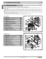
Monoblocchi
Fireboxes
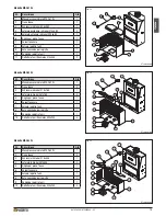
MA 260 SL
MA 262 SL
MA 264 SL
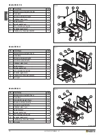
MA 260B SL
MA 263 SL
MA 265 SL
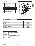
MA 261 SL
MA 263B SL
MA 266 SL
Italiano
English


