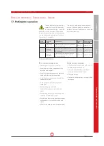
OPERATING AND INSTALLATION INSTRUCTIONS LG 250 A
PAGE 42
Changes reserved
U
S
ER
G
ENER
A
L
S
P
EC
IA
LIS
T
P
ER
S
O
NNEL
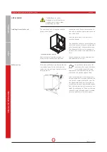
The unit's connectors must be connected
to air duct connections. Airtightness and
vibration isolation must be ensured.
Air pipes and attachments such as sound
absorbers etc. may only be attached to
the ventilation unit using adequately
dimensioned elements for mounting to
suitable solid wall or ceiling structural
components.
Avoid using flexible hoses for connections
to the unit. When making connections,
ensure in particular that no tools or
assembly material will fall into the
connections to the unit or onto the
unit itself. This could cause damage
components such as fan blades. Air
duct and installation components must
be suitably and adequately insulated in
accordance with project specifications.
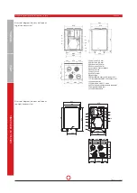
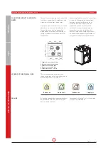
CONNECTING AIR DUCTS AND COMPO-
NENTS
1. Supply air connection ø160 mm
2. Extract air connection ø160 mm
3. Outdoor air connection ø160
4. Exhaust air connection ø160
5. Cable inlets 4 x M16 / 1 x M12
1
2
3
4
3
1
4
2
1
2
3
4
3
1
4
2
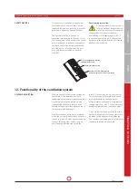
SEALING
All sealing required during assembly must
be performed using neutral-curing and
non-corrosive sealants.
For example: Sikaflex®-221, silicone-free
(item no. 12DMAUSSEN).
1
2
3
4
13
13
247
282
143
13
0
27
2
19
1
181
276
215
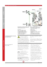
1 Zu
luft ø 160 mm
2 Abluft
ø 160 mm
3 Außenluft
ø 160 mm
4 Fortluft
ø 160 mm
5 Gegenstromwärmetauscher
6 Abluftventilator
7 Zuluftventilator
8 Steuerung
9 Bypassklappe
10 Abluftfilter G4
11 Außenluftfilter F7
12 Kondensatwanne
13 Kabeleinführung 4 x M16 / 1 x M12
14 PTC-Elektrovorheizregister (optional)
15 Höhenverstellbare Füße
16 Kondensatstutzen
Abbildung:
LG 250 A-L (linke Ausführung)
Aufbauskizze (Stand- oder Wandmontage, linke Ausführung)
Extract air
Outdoor air
Exhaust air
Supply air
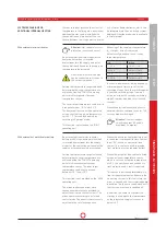
LEGEND FOR THE SYMBOLS USED
The corresponding air type for each
connection piece on the ventilation unit is
marked by means of a symbol.


