OPERATING AND INSTALLATION INSTRUCTIONS LG 250 A
PAGE 46
Changes reserved
U
S
ER
G
ENER
A
L
S
P
EC
IA
LIS
T
P
ER
S
O
NNEL
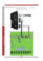
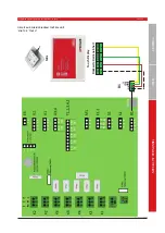
The gateway communicates via the
Modbus RTU connection of the building
control system (BCS). Therefore either the
gateway or the Modbus RTU can be used
for the BCS.
(see Page 11)
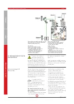
ELECTRICAL WIRING DIAGRAM GATEWAY
A
1
B
2
GN
D
3
GN
D
2
24
VD
C
1
1
2
3
1
2
3 4
1
2
1
2
3 4
1
2
3
4
U3
U4
1
2 T1
1
2
3
1
2
3
1
2
3 4
1 2 3
N
L
1 2 3
1 2 3
1 2 3
1 2 3
1 2 3
PE
1 2 3
1 2 3 4
Rel
ay
Rel
ay
Rel
ay
Rel
ay
Rel
ay
Relay
Relay
FUS
E2
Sic
he
rung
T
4A
H
FUS
E1
Si
che
rung
T
10
AH
K2
K2
K6
K5
K4
K3
K1
E3
U2
U1
U3
,4
T1,
2,
3,
4,
5
M1
S2
S1
B1
St
ift
ko
nta
kte
E-
VH
R SSR
3
4 T2
5
6 T3
7
8 T4
9
10 T5
Kn
op
fze
lle
n-
Ba
tte
rie
3V
, T
yp
: C
R2032
E1,
2
1
2
3
E1
E2
GND
SD
-CAR
D
Et
he
rne
t
RJ
45
Gr
een
LE
D l
ig
ht
s
w
he
n i
nt
er
ne
t
con
ne
ct
ion
is
es
tab
lis
he
d.
M
odbus
R
S 48
5
Su
pp
ly v
ol
ta
ge
+
GND
B
GND
A
LA
N R
J45
LAN
-Ka
bel

